

Project Overview
Temperature-Controlled Fan with Arduino Uno and DHT11: Build a proportional thermostat where an Arduino Uno reads a DHT11 sensor, shows temperature, humidity, set point, and fan percentage on a 16x2 I2C LCD, and ramps a DC fan with PWM through an L298N motor driver based on a potentiometer set-point knob.
- Time: ~45 minutes
- Skill level: Beginner-Intermediate
- What you will build: A proportional temperature-to-fan controller with an adjustable set point, a hysteresis band so the fan does not chatter, and a live LCD readout.

Parts List
From ShillehTek
- Arduino Uno R3 Super Starter Kit - includes a potentiometer and a DC motor to test with
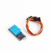
- DHT11 Temperature & Humidity Sensor - measures temperature and humidity
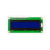
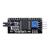
- LCD1602 16x2 Display + PCF8574 I2C Adapter - shows readings and fan percentage over I2C
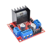
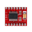
- L298N Motor Driver (or the TB6612FNG for less heat) - switches the fan supply using Arduino PWM
- LM2596 Buck Converter - optional, to run a 12 V fan from a laptop supply
- 830-Point Breadboard - prototyping
- Dupont Jumper Wires - wiring
External
- A 5 V or 12 V brushless DC fan (a 2-wire PC case fan is perfect) and a matching power supply
Note: never drive a fan straight from an Arduino pin. Pins give 20-40 mA and a fan wants hundreds. The L298N takes the PWM signal on its enable pin and switches the fan's own supply. Use a 2-wire (or 3-wire, ignoring the tach wire) fan; 4-wire PWM fans have their own control input and want a 25 kHz signal instead.
Step-by-Step Guide
Step 1 - Wire Sensor, LCD and Knob
Goal: The inputs and the display.
What to do: DHT11: DATA → D2, VCC → 5V, GND → GND. I2C LCD: SDA → A4, SCL → A5, VCC → 5V, GND → GND. Potentiometer: outer pins to 5V and GND, wiper → A0.
Expected result: Three inputs on three pins, one display on the I2C bus.
Step 2 - Wire the Fan Through the L298N
Goal: Safe PWM power for the fan.
What to do: L298N: ENA → D9 (PWM), IN1 → D7, IN2 → D8, OUT1/OUT2 → fan wires (red to OUT1 for the polarity we will set), +12V terminal → fan supply positive (5-12 V), GND → supply negative AND Arduino GND. Remove the ENA jumper so D9 controls it. Leave the 5V-enable jumper on if your supply is 12 V; the board then makes its own logic 5 V.
Expected result: The fan spins only when the Arduino says so.
Step 3 - The Sketch
Goal: Read the DHT11, compute fan speed with hysteresis and proportional control, and show everything on the LCD.
Code:
#include <DHT.h>
#include <LiquidCrystal_I2C.h>
DHT dht(2, DHT11);
LiquidCrystal_I2C lcd(0x27, 16, 2);     // try 0x3F if the screen stays blank

const int POT = A0, ENA = 9, IN1 = 7, IN2 = 8;
const float BAND = 4.0;                 // degrees above set point for 100 % fan
const float HYST = 0.5;                 // fan turns off only 0.5 C below set point
bool fanOn = false;

void setup() {
  dht.begin(); lcd.init(); lcd.backlight();
  pinMode(ENA, OUTPUT); pinMode(IN1, OUTPUT); pinMode(IN2, OUTPUT);
  digitalWrite(IN1, HIGH); digitalWrite(IN2, LOW);   // fixed direction
}

void loop() {
  float setPt = 15.0 + analogRead(POT) * 25.0 / 1023.0;   // knob: 15 ... 40 C
  float t = dht.readTemperature();
  float h = dht.readHumidity();
  if (isnan(t)) { lcd.setCursor(0, 0); lcd.print("DHT error       "); delay(2000); return; }

  // hysteresis: switch on above set point, off only below set point - HYST
  if (t >= setPt) fanOn = true;
  else if (t < setPt - HYST) fanOn = false;

  // proportional speed: 0 % at the set point, 100 % at set point + BAND
  int pct = 0;
  if (fanOn) pct = constrain((t - setPt) / BAND * 100.0, 25, 100);   // never below 25 % (fans stall)
  analogWrite(ENA, map(pct, 0, 100, 0, 255));

  lcd.setCursor(0, 0);
  lcd.print("T:"); lcd.print(t, 1); lcd.print("C H:"); lcd.print((int)h); lcd.print("% ");
  lcd.setCursor(0, 1);
  lcd.print("Set:"); lcd.print(setPt, 1); lcd.print(" Fan:"); lcd.print(pct); lcd.print("%  ");
  delay(2000);                          // DHT11 minimum interval
}
What to do: Install the Adafruit DHT library (plus Unified Sensor) and LiquidCrystal_I2C, upload, then turn the knob below the current room temperature.
Expected result: The LCD shows the temperature, humidity, set point and fan %. Dial the set point under room temperature and the fan starts; the further below, the faster it spins, until 100 % four degrees past the set point. Dial it above and the fan stops, but only once the temperature is half a degree under the set point, so it never flutters on the threshold.
Step 4 - Test the Control Loop
Goal: See it react.
What to do: Set the knob about 1 °C above room temperature. Cup the DHT11 in your hands for 30 seconds (it warms slowly; it is a slow sensor). Watch the fan start at 25 %, climb as the reading rises, then fall back and switch off after you let go and the reading drops through the hysteresis band.
Expected result: A controller that responds to temperature in proportion, not just on/off.
Step 5 - Make It a Real Appliance
Goal: From breadboard to useful.
What to do: Aim the fan at what you are cooling (a 3D-printer enclosure, a router shelf, a terrarium) and mount the DHT11 in the airflow's return path, not right in front of the fan. Swap the DHT11 for a DS18B20 or DHT22 for better resolution, or save the set point to EEPROM so it survives power loss. For a heater instead of a fan, flip the logic: turn on below the set point.
Expected result: A proportional thermostat you can drop into any project that gets too warm.
Conclusion
With an Arduino Uno, a DHT11, a set-point knob, hysteresis, and PWM (instead of a simple relay), you built a temperature controller that ramps a DC fan smoothly as conditions change. The same structure can be adapted for humidity control, heaters, pumps, and lighting by swapping the sensor and actuator.
Want the exact parts used in this build? Grab them from ShillehTek.com. If you want help customizing this project or building something for your product, check out our IoT consulting services.
Reference credit: this version is based on the original guide by ronfrtek on Hackster.io.





.png?v=25000753014097803521791168436)

.png?v=68677308723310773341791168436)


