

Project Overview
Turn sound into light with an ESP32, an INMP441 microphone, and a MAX7219 LED matrix. The microphone picks up nearby sound, the ESP32 analyzes it, and the display turns that information into moving bars. It is a straightforward way to see what a digital microphone can do in an electronics project.
In the short demo below, the matrix reacts first to a steady tone and then to a tap on the table. A tone concentrates energy around its frequency, while a tap produces a brief response across a wider range. The sketch uses a fast Fourier transform (FFT) to separate the incoming audio into frequency ranges for the display.
- Time: ~1 hour
- Skill level: Intermediate
- What you will build: A sound-reactive 32-column LED spectrum visualizer.
Watch the demo on YouTube Shorts
This is a visualizer, not a calibrated sound-level meter. The bars show relative frequency content, and automatic gain adjustment keeps the response visible as the sound level changes.
Parts List
From ShillehTek
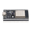
- ESP32 Dev Board, 38-Pin USB-C — reads the microphone and drives the matrix.
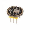
- INMP441 I2S Microphone Module — sends digital audio to the ESP32.
- MAX7219 4-in-1 LED Matrix — four 8 × 8 modules form a 32 × 8 display.
- 400-Point Breadboard — holds the prototype connections.
- Dupont Jumper Wires — connect the microphone, ESP32, and display.
External
- A USB data cable and a computer running Arduino IDE.
- A 74AHCT125 buffer or equivalent 3.3 V-input-compatible, 5 V-output logic buffer for the matrix's DIN, CLK, and CS signals.
- A suitable regulated 5 V supply for the matrix if the board's USB-powered 5 V rail cannot supply it reliably.
- A phone or speaker for playing a test tone.
Step-by-Step Guide
Step 1 — Connect the INMP441 microphone
Goal: Send digital audio to the ESP32 over I2S.
What to do: With power disconnected, wire the microphone using the table below. These GPIO numbers match the classic ESP-WROOM-32 board and the sketch in this guide.
| INMP441 pin | ESP32 connection |
|---|---|
| VDD | 3V3 |
| GND | GND |
| L/R | GND — selects the left channel |
| WS | GPIO 25 |
| SCK | GPIO 26 |
| SD | GPIO 33 |
Power the INMP441 from 3.3 V, not 5 V. It is an I2S digital microphone: its SD pin carries audio data and does not connect to an analog input.
Expected result: The microphone is wired for the left-channel, 32-bit I2S configuration used by the sketch.
Step 2 — Connect the MAX7219 matrix
Goal: Give the display power and connect its serial input to the ESP32.
What to do: Use the matrix's input header, labeled DIN. Keep all grounds connected together.
| MAX7219 pin | Connection |
|---|---|
| VCC | Regulated 5 V; use the board's 5 V/VIN rail only if it provides a suitable USB-powered output |
| GND | Common ground with the ESP32 and microphone |
| DIN | GPIO 23 through a 3.3 V-to-5 V logic buffer |
| CS / LOAD | GPIO 5 through a 3.3 V-to-5 V logic buffer |
| CLK | GPIO 18 through a 3.3 V-to-5 V logic buffer |
The MAX7219's specified minimum logic-high input is 3.5 V when powered at 5 V. Direct ESP32 signals can work with some modules, but 3.3 V is below that specification. For a reliable build, use three channels of a 5 V-powered 74AHCT125, with its used output-enable inputs held low and supply decoupling as shown in its datasheet. If using a separate display supply, share ground and avoid connecting competing 5 V supplies together.
Expected result: The display has a stable supply and receives DIN, CS, and CLK at suitable logic levels. Start with low brightness to limit current draw.
Step 3 — Set up Arduino IDE
Goal: Install the board support and libraries required by the sketch.
What to do: Install the esp32 board package by Espressif Systems through Boards Manager and use a 3.x release. Select the board and serial port for your ESP32. For the classic board linked above, ESP32 Dev Module is the usual board selection.
In Library Manager, install arduinoFFT by Enrique Condes, version 2.x, and MD_MAX72XX by majicDesigns. The ESP_I2S.h and SPI support come with the ESP32 board package.
Expected result: Arduino IDE can find all four headers at the top of the sketch. This version uses the current ESP_I2S.h API; it is not written for the older ESP32 core 2.x I2S driver.
Step 4 — Upload the visualizer sketch
Goal: Capture audio, calculate its spectrum, and draw the bars.
What to do: Copy the complete sketch below into a new Arduino sketch and upload it. It uses 1,024 samples per FFT at 44.1 kHz, then maps the results to 32 display columns. The lower-frequency ranges share some FFT bins, so this is a compact visual display rather than a precision spectrum analyzer.
The code uses the classic ESP32's default hardware SPI pins: GPIO 23 for MOSI and GPIO 18 for SCK. It assumes a common FC-16-style four-module matrix.
/*
  ShillehTek: ESP32 sound-reactive LED matrix
  Classic ESP32 / ESP-WROOM-32, Arduino-ESP32 core 3.x
  Libraries: arduinoFFT 2.x, MD_MAX72XX

  INMP441: VDD=3V3, GND=GND, L/R=GND,
           WS=GPIO25, SCK=GPIO26, SD=GPIO33
  MAX7219: VCC=5V, GND=common ground,
           DIN=GPIO23, CS=GPIO5, CLK=GPIO18
  Use a suitable 3.3 V-to-5 V logic buffer on DIN, CS, CLK.
*/

#include <ESP_I2S.h>
#include <arduinoFFT.h>
#include <MD_MAX72xx.h>
#include <SPI.h>

// ---- pins ----
#define PIN_I2S_WS   25
#define PIN_I2S_SCK  26
#define PIN_I2S_SD   33
#define PIN_CS        5

// ---- display ----
// FC16_HW fits the common blue 4-in-1 modules. If your bars look scrambled
// (not just mirrored), try GENERIC_HW or DR1CR0RR0_HW here.
#define HARDWARE_TYPE MD_MAX72XX::FC16_HW
#define MAX_DEVICES   4
#define BRIGHTNESS    2      // 0-15. Start low (1-3) for a readable display and lower current.
bool FLIP_COLUMNS  = false;  // set true if spectrum runs right-to-left
bool FLIP_VERTICAL = false;  // set true if bars hang from the top

// ---- audio / FFT ----
const uint32_t SAMPLE_RATE = 44100;
const uint16_t NSAMP       = 1024;
const uint8_t  NBANDS      = 32;      // one display range per matrix column
const float    FMIN        = 60.0;    // Hz, bottom of lowest band
const float    FMAX        = 12000.0; // Hz, top of highest band

I2SClass i2s;
MD_MAX72XX mx = MD_MAX72XX(HARDWARE_TYPE, PIN_CS, MAX_DEVICES);

double vReal[NSAMP];
double vImag[NSAMP];
ArduinoFFT<double> FFT(vReal, vImag, NSAMP, (double)SAMPLE_RATE);

int32_t rawBuf[NSAMP];
uint16_t bandLo[NBANDS], bandHi[NBANDS];

float barLevel[NBANDS] = {0};   // smoothed bar height, 0..8
float peakPos[NBANDS]  = {0};   // falling peak dot, 0..8
float autoGain = 1000.0;        // rolling loudness reference

void setup() {
  Serial.begin(115200);

  // Display
  mx.begin();
  mx.control(MD_MAX72XX::INTENSITY, BRIGHTNESS);
  mx.clear();

  // Mic: standard I2S, 32-bit slots, mono (left channel, L/R pin -> GND)
  i2s.setPins(PIN_I2S_SCK, PIN_I2S_WS, -1, PIN_I2S_SD);
  if (!i2s.begin(I2S_MODE_STD, SAMPLE_RATE, I2S_DATA_BIT_WIDTH_32BIT,
                 I2S_SLOT_MODE_MONO, I2S_STD_SLOT_LEFT)) {
    Serial.println("I2S init failed — check wiring");
    while (true) delay(100);
  }

  // Precompute log-spaced band edges (60 Hz .. 12 kHz over 32 columns)
  for (uint8_t b = 0; b < NBANDS; b++) {
    float fLo = FMIN * powf(FMAX / FMIN, (float)b / NBANDS);
    float fHi = FMIN * powf(FMAX / FMIN, (float)(b + 1) / NBANDS);
    bandLo[b] = max(1, (int)(fLo * NSAMP / SAMPLE_RATE));
    bandHi[b] = max((int)bandLo[b], (int)(fHi * NSAMP / SAMPLE_RATE));
  }

  // Little wake-up sweep so you know the display works
  for (int c = 0; c < NBANDS; c++) {
    mx.setColumn(c, 0xFF); delay(12); mx.setColumn(c, 0x00);
  }
}

void loop() {
  // ---- 1. capture one FFT frame from the mic ----
  size_t got = i2s.readBytes((char*)rawBuf, sizeof(rawBuf));
  if (got < sizeof(rawBuf)) return;

  double mean = 0;
  for (int i = 0; i < NSAMP; i++) {
    vReal[i] = (double)(rawBuf[i] >> 14);  // INMP441 data sits in the top 24 bits
    vImag[i] = 0;
    mean += vReal[i];
  }
  mean /= NSAMP;
  for (int i = 0; i < NSAMP; i++) vReal[i] -= mean;  // remove DC offset

  // ---- 2. FFT ----
  FFT.windowing(FFTWindow::Hamming, FFTDirection::Forward);
  FFT.compute(FFTDirection::Forward);
  FFT.complexToMagnitude();

  // ---- 3. fold bins into 32 log-spaced bands ----
  float bands[NBANDS];
  float frameMax = 0;
  for (uint8_t b = 0; b < NBANDS; b++) {
    float sum = 0;
    for (uint16_t k = bandLo[b]; k <= bandHi[b] && k < NSAMP / 2; k++) sum += vReal[k];
    bands[b] = sum / (bandHi[b] - bandLo[b] + 1);
    frameMax = max(frameMax, bands[b]);
  }

  // ---- 4. auto-gain: adapts to changes in signal level ----
  if (frameMax > autoGain) autoGain = frameMax;          // jump up instantly
  autoGain = max(600.0f, autoGain * 0.995f);             // decay slowly; keep a minimum scaling reference

  // ---- 5. bars: instant attack, smooth 0.55-row-per-frame fall ----
  for (uint8_t b = 0; b < NBANDS; b++) {
    float h = 8.0f * bands[b] / autoGain;                // 0..8
    h = constrain(h, 0.0f, 8.0f);
    if (h > barLevel[b]) barLevel[b] = h;                // rise fast
    else                 barLevel[b] = max(h, barLevel[b] - 0.55f);  // fall smooth

    if (barLevel[b] >= peakPos[b]) peakPos[b] = barLevel[b];         // peak dot rides up
    else                           peakPos[b] = max(0.0f, peakPos[b] - 0.18f); // drifts down
  }

  // ---- 6. draw ----
  for (uint8_t b = 0; b < NBANDS; b++) {
    uint8_t h = (uint8_t)round(barLevel[b]);
    uint8_t colBits = (h == 0) ? 0 : (uint8_t)(0xFF00 >> h);  // bar grows from bottom (row 7 = lit first)
    uint8_t p = (uint8_t)round(peakPos[b]);
    if (p > h && p >= 1 && p <= 8) colBits |= (0x100 >> p);   // lone peak dot above the bar
    if (FLIP_VERTICAL) colBits = reverseBits(colBits);
    uint8_t col = FLIP_COLUMNS ? b : (NBANDS - 1 - b);        // low freqs on the left
    mx.setColumn(col, colBits);
  }
}

uint8_t reverseBits(uint8_t v) {
  v = (v & 0xF0) >> 4 | (v & 0x0F) << 4;
  v = (v & 0xCC) >> 2 | (v & 0x33) << 2;
  v = (v & 0xAA) >> 1 | (v & 0x55) << 1;
  return v;
}
Expected result: On startup, a short sweep travels across the matrix. After that, the bars respond to nearby sound. Open Serial Monitor at 115200 baud if you need to check the I2S startup message.
Step 5 — Try the tone-and-tap demo
Goal: See how different sounds appear on the display.
What to do: Play a steady tone from a speaker near the microphone at a comfortable volume. Change the pitch and watch the strongest response move across the matrix. Stop the tone, then lightly tap the table near the setup to create a short transient, as shown in the YouTube Short.
Expected result: A steady tone gives a more concentrated pattern, while the tap produces a brief burst. Room noise, speaker distortion, and vibration through the table can all affect the display. Because the sketch adjusts gain automatically, bar height is not a fixed measure of loudness.
Step 6 — Adjust the display and troubleshoot
Goal: Make the bars readable on your particular matrix.
-
Too bright: Lower
BRIGHTNESS. The sketch starts at 2 on the MAX7219's 0–15 intensity scale. -
Mirrored or upside down: Change
FLIP_COLUMNSorFLIP_VERTICAL. If individual modules look scrambled, checkHARDWARE_TYPEagainst your matrix's wiring layout. - Startup sweep works, but sound does not: Recheck the microphone's WS, SCK, and SD wires, its 3.3 V supply, and the L/R-to-GND connection.
- Random pixels or resets: Check the 5 V supply, common ground, logic buffer, and matrix input header. Keep wiring short and test at low brightness.
-
Bars remain active in a quiet room: The microphone can still hear background sound. Increasing the
600.0fminimum gain reference reduces the visible response to weak signals; that value is not a calibrated noise threshold. - Compile errors: Confirm ESP32 core 3.x and arduinoFFT 2.x are installed. The older arduinoFFT API uses different names.
Expected result: You have a stable display that responds clearly to sound and is oriented correctly for your setup.
Conclusion
The INMP441 gives the ESP32 a digital audio input, and the MAX7219 matrix makes the result easy to see. With the basic visualizer working, you can experiment with the frequency range, falling peak dots, or different bar animations. The sketch processes audio locally; it does not save recordings or need Wi-Fi.
Want the parts for this build? Find the microphone, ESP32, and matrix at ShillehTek.com. If you need help adapting a sensor project for a product or custom installation, explore our IoT consulting services.





.png?v=25000753014097803521791168436)

.png?v=68677308723310773341791168436)


