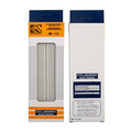
1660-Point Solderless Breadboard Assembly with Base and 3 Power TerminalsDefault Title · $13.99 · In stock
Overview
This is a large solderless breadboard assembly with 1660 tie points, mounted on a rigid base with three binding posts for power. Component leads and jumper wires push into the holes, so you can build, test and rearrange circuits without soldering.
Two full-size terminal strips give room for a microcontroller board, several chips and plenty of modules at once, and four power strips run alongside them. It suits bench development, classroom experiments and larger Arduino, ESP32, Raspberry Pi and Pico prototypes. No power supply is included.
At a Glance
Type
Solderless breadboard on a base
Tie Points
1660
Terminal Strips
2 strips, 1260 points
Power Strips
4 strips, 400 points
Wire Size
20 to 29 AWG
Base
215 × 130 mm, 3 binding posts
Specifications
Parameter
Value
Model
ZY-204
Tie points
1660 in total
Terminal strips
2 strips, 1260 points together
Distribution (power) strips
4 strips, 400 points together
Terminal strip connections
Columns of 5 holes on each side of the center channel
Power strip connections
Holes joined along the length of the strip
Wire size
20 to 29 AWG solid wire
Hole pitch
2.54 mm (0.1 in)
Base
215 × 130 mm, with four feet
Binding posts
3 (black, red and blue)
In the box
Base-mounted breadboard, three binding posts, four feet
Power supply
Not included
Wiring Guide
Bring power in at the binding posts, run a wire from each post to a power strip, then feed your circuit from the strips. Do not assume the posts are connected to the strips: make that link yourself with a jumper wire. Before you rely on a power strip, check it from end to end with a multimeter, because on many large breadboards each line is split in the middle.
Using It With an Arduino
Item
How to Connect
Arduino Nano
Plugs in across the center channel of a terminal strip
Arduino Uno
Sits beside the breadboard: run jumper wires from its headers
Power
5V and GND from the Arduino to a pair of power strip lines
One ground: If you use more than one supply, join all the ground lines together so every part shares the same reference.
Using It With an ESP32
Item
How to Connect
ESP32 dev board
Plugs in across the center channel of a terminal strip. Wide boards may leave free holes on one side only
Power
3V3 and GND from the ESP32 to a pair of power strip lines
3.3 V logic: ESP32 pins work at 3.3 V. Keep a 5 V line on a separate power strip and label it, so it cannot reach a GPIO pin by mistake.
Using It With a Raspberry Pi
Item
How to Connect
GPIO pins
Female-to-male jumper wires from the 40-pin header to the breadboard
Power
3V3 (Pin 1) and GND (Pin 6) to a pair of power strip lines
3.3 V only: Raspberry Pi GPIO pins are not 5 V tolerant. Keep any 5 V line on the breadboard away from wires that lead back to GPIO pins.
Using It With a Raspberry Pi Pico
Item
How to Connect
Pico with headers
Plugs in across the center channel of a terminal strip, with free holes beside every pin
Power
3V3(OUT) (Pin 36) and GND (Pin 38) to a pair of power strip lines
Two boards: With two terminal strips there is room for a Pico on one and sensors, displays or a second board on the other.
Frequently Asked Questions
How are the holes connected?
On the two wide terminal strips, the holes are joined in short columns of five on each side of the center channel. On the four narrow power strips, the holes are joined lengthwise along the strip. Nothing connects one strip to another until you add a jumper wire.
Are the binding posts connected to the power strips?
Do not assume so. Treat the posts as separate terminals and run your own wire from each post to the power strip you want it to feed. That also lets you decide which post carries which voltage, for example red for 5 V, blue for 3.3 V and black for ground.
Are the power strips continuous from end to end?
Check before you rely on it. On many large breadboards each power line is split into two halves at the middle of the strip. Measure continuity from one end to the other with a multimeter. If there is a break, bridge it with a short jumper, or use the two halves for different voltages.
What wire size fits?
Solid wire from 20 to 29 AWG. Standard 22 AWG solid hookup wire and ready-made jumper wires are the best fit. Thicker leads can stretch the contacts so that thin wires no longer grip.
Is a power supply included?
No. Connect your own bench supply, battery pack or power module to the binding posts or straight to the power strips. Set and check the voltage before you connect it to a circuit.
How much current can it carry?
No rating is published for this board, so be conservative. Breadboard contacts are thin spring clips suited to signals, sensors, LEDs and small modules. Wire motors, heaters and other loads of an amp or more directly to the supply, and never use a breadboard for mains voltage.
How do I fit and use the binding posts?
If the posts and feet arrive loose, mount each post in a hole in the base and tighten its nut, then attach the four feet to the underside. To connect a wire, loosen the post cap, put the stripped end through the hole in the post or under the cap, and tighten it again.
Reference documents for the 1660-Point Solderless Breadboard Assembly with Base and 3 Power Terminals. This manual covers wiring and code; the documents below carry the full electrical specifications.