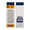
SYB-170 170-Point Mini Solderless BreadboardSingle · $2.50 · In stock
Overview
The SYB-170 is a mini solderless breadboard with 170 tie points. Push component leads and jumper wires into the holes to build a circuit, and pull them out to change it. Nothing is soldered, so the board and your parts can be reused again and again.
Its small size makes it ideal for a single sensor, a small test circuit or a compact build next to an Arduino, ESP32, Raspberry Pi or Pico. Interlocking tabs on the sides let you join several boards into a larger work area. It is available as a single board or as a pack of five.
At a Glance
Type
Mini solderless breadboard
Tie Points
170
Layout
2 blocks of 17 × 5 holes
Power Rails
None
Hole Pitch
2.54 mm (0.1 in)
Pack Options
Single or 5-pack
Specifications
Parameter
Value
Model
SYB-170
Tie points
170
Layout
Two blocks of 17 columns × 5 holes, separated by a center channel
Internal connections
The 5 holes of each column are joined; the two blocks are separate
Power rails
None
Hole pitch
2.54 mm (0.1 in)
Center channel
Fits DIP chips, one row of pins in each block
Expansion
Interlocking side tabs join boards together
Color
White
Pack options
Single board or pack of five
Wiring Guide
Each short column of five holes is one electrical node: everything pushed into the same column is connected. The two blocks on either side of the center channel are not connected to each other. There are no power rails, so pick two columns as your own power and ground lines.
Using It With an Arduino
Board
How to Connect
Arduino Nano
Plugs in across the center channel: its 15 pins per side fit the 17 columns, with free holes beside each pin
Arduino Uno
Sits beside the breadboard: run jumper wires from its headers
Power lines: Run 5V to one free column and GND to another, then feed your parts from those two columns.
Using It With an ESP32
Board
How to Connect
Full-size ESP32 dev boards
Too long or too wide to plug in usefully: place the board beside the breadboard and use jumper wires
Small ESP32 boards
Fit if they have 17 pins per side or fewer and leave free holes beside the pins
3.3 V logic: ESP32 pins work at 3.3 V. Feed sensors on the breadboard from the 3V3 pin unless a part needs 5 V and has 3.3 V compatible signals.
Using It With a Raspberry Pi
Connection
How
GPIO pins
Female-to-male jumper wires from the 40-pin header to the breadboard
Power
3V3 (Pin 1) and GND (Pin 6) to two columns of your choice
3.3 V only: Raspberry Pi GPIO pins are not 5 V tolerant. Keep any 5 V on the breadboard away from wires that lead back to GPIO pins.
Using It With a Raspberry Pi Pico
Item
How to Connect
Raspberry Pi Pico
Has 20 pins per side, so it is too long for one 17-column board: connect it with jumper wires or use a larger breadboard
Sensors and breakout boards
Plug straight in, one pin per column
Power lines: Run 3V3(OUT) (Pin 36) and GND (Pin 38) to two free columns and feed your parts from there.
Frequently Asked Questions
How are the holes connected inside?
In short columns of five. Each block has 17 columns, and the five holes in a column share one metal clip. The center channel separates the two blocks, so a column on one side is not connected to the column facing it.
Does it have power rails?
No. A 170-point board is too small for separate power rails. Choose one column for power and another for ground and run jumper wires from them, or use it next to a larger breadboard that has rails.
What wire should I use?
Solid-core hookup wire of about 22 AWG, or ready-made jumper wires with pin ends. Bare stranded wire and very thin wire do not make reliable contact, and oversized leads can stretch the clips so that normal wires no longer grip.
Can I plug chips into it?
Yes. DIP chips sit across the center channel with one row of pins in each block, which leaves four free holes beside every pin for your connections.
How do I join several boards?
Slide the tabs on the side of one board into the slots of the next. The boards then hold together as one work area. The join is mechanical only: no holes are connected between boards, so use jumper wires to carry power and signals across.
How much current and voltage can it take?
Treat it as a tool for low-voltage, low-current electronics: logic signals, sensors, LEDs and small modules. Breadboard contacts are thin spring clips and are not meant for motors drawing amps or for anything connected to mains voltage. Wire high-current paths directly instead.
Why is my circuit unreliable on the breadboard?
The usual causes are a lead that is not pushed in fully, two parts sharing a column by mistake, or a worn contact that has lost its grip. Reseat the part, move it to a fresh column and check each connection against your diagram. Long, loose wires also pick up noise in fast or sensitive circuits.