Overview
The Raspberry Pi Debug Probe is a small USB adapter for debugging and programming microcontrollers. It gives your computer two things at once: an SWD debug connection for loading and stepping through code, and a UART serial bridge for reading the target's console output. It was designed for the Raspberry Pi Pico family and also works with other Arm microcontrollers that use SWD.
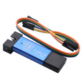
The probe speaks the standard CMSIS-DAP protocol, so OpenOCD, GDB and the Raspberry Pi Pico extension for VS Code work with it without vendor drivers. The kit includes the probe in its case, a USB cable and three debug cables for boards with a debug socket, header pins or sockets.
At a Glance
Specifications
| Parameter | Value |
| Probe | Raspberry Pi Debug Probe, based on the RP2040 |
| Functions | USB to SWD debug and USB to UART serial |
| Debug protocol | CMSIS-DAP, supported by OpenOCD and GDB |
| D connector | 3-pin JST-SH: SC (SWCLK), GND, SD (SWDIO) |
| U connector | 3-pin JST-SH: TX, GND, RX |
| I/O voltage | 3.3 V |
| Target power | Not supplied: power the target separately and share ground |
| Wire colors, D port | Orange SWCLK, black GND, yellow SWDIO |
| Wire colors, U port | Orange TX (from the probe), black GND, yellow RX (to the probe) |
| Board size | 22 × 32 mm |
| Kit contents | Probe in case, USB cable, and three cables: JST-SH to JST-SH, JST-SH to male pins, JST-SH to female sockets |
Wiring Guide
The probe has two 3-pin ports: D for SWD debug and U for UART serial. Connect either or both to the target, then power the target from its own USB cable or supply. The probe does not power the target, and all signals are 3.3 V.
SWD Debug Port (D) to a Pico
A Pico H has a 3-pin debug socket: plug the JST-SH to JST-SH cable straight in. On a Pico with debug header pins, use the JST-SH to female sockets cable. A plain Pico has three debug pads at the end of the board, which need pins soldered on first.
| Probe Wire | Pico Debug Pin | Signal |
|---|---|---|
| Orange | SWCLK | Clock |
| Black | GND | Ground |
| Yellow | SWDIO | Data |
UART Serial Port (U) to a Pico
| Probe Wire | Pico Pin | Direction |
|---|---|---|
| Orange (TX) | GP1 (Pin 2), UART0 RX | Probe to Pico |
| Yellow (RX) | GP0 (Pin 1), UART0 TX | Pico to probe |
| Black | GND (Pin 3) | Ground |
Other SWD Targets
The probe is a generic CMSIS-DAP adapter, so it can debug other Arm Cortex-M boards that expose SWD, as long as the target runs at 3.3 V and your tools have a configuration for that chip.
| Probe Signal | Target Pin |
|---|---|
| SC (orange, D port) | SWCLK |
| SD (yellow, D port) | SWDIO |
| GND (black) | GND |
| TX and RX (U port) | The target's UART RX and TX, optional |
Software Setup
The probe needs no vendor driver. It appears to the computer as a CMSIS-DAP debug adapter plus a USB serial port.
| Task | Tool |
|---|---|
| Flash and debug from the command line | OpenOCD with interface/cmsis-dap.cfg, plus GDB |
| Flash and debug from an editor | Raspberry Pi Pico extension for VS Code |
| Serial console | Any terminal program at 115200 baud, for example minicom |
Code Examples
View or download this product's example code on GitHub.
The first block installs the tools on Raspberry Pi OS, Debian or Ubuntu and flashes an ELF file to a Pico. SWD loads ELF files, not UF2 files. For a Pico 2, use target/rp2350.cfg with an OpenOCD build that supports the RP2350. The second block opens the probe's serial port.
Flash a Program Over SWD (OpenOCD)
# Install the tools (Raspberry Pi OS, Debian, Ubuntu)
sudo apt install openocd gdb-multiarch

# Flash an ELF file to a Pico over SWD, then reset and run it
openocd -f interface/cmsis-dap.cfg -f target/rp2040.cfg -c "adapter speed 5000" -c "program blink.elf verify reset exit"
Open the Serial Console
# Open the probe's UART at 115200 baud
# The port name can differ - list the candidates with: ls /dev/ttyACM*
sudo apt install minicom
minicom -b 115200 -o -D /dev/ttyACM0