Overview
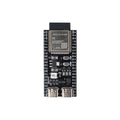
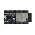
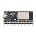
This development board carries an ESP32-S3 module in the N16R8 configuration: 16 MB of flash and 8 MB of PSRAM. The ESP32-S3 is a dual-core 240 MHz microcontroller with Wi-Fi, Bluetooth Low Energy, native USB and plenty of GPIO, which makes it a strong choice for audio, displays, cameras and other memory-hungry projects.
The board has two USB-C ports (one for serial programming, one wired to the chip's native USB), BOOT and RST buttons, an addressable RGB LED, a PCB antenna and an IPEX socket on the module. The headers come pre-soldered, so it drops straight into a breadboard. You can program it with the Arduino IDE, ESP-IDF or MicroPython.
At a Glance
Specifications
| Parameter | Value |
| Module | ESP32-S3 N16R8: 16 MB flash, 8 MB octal PSRAM |
| CPU | Dual-core Xtensa LX7, up to 240 MHz |
| Wireless | Wi-Fi 802.11 b/g/n at 2.4 GHz, Bluetooth 5 LE |
| COM port | USB-C through a CH343P USB-to-serial chip: uploads and serial monitor |
| USB port | USB-C on the ESP32-S3 native USB pins, GPIO 19 and 20 |
| Power input | 5 V through either USB-C port or the 5Vin pin |
| Logic level | 3.3 V on every GPIO, not 5 V tolerant |
| On-board LED | WS2812 RGB LED on GPIO 48 |
| Buttons | BOOT (GPIO 0) and RST |
| Antenna | PCB antenna, plus an IPEX socket on the module |
| Reserved pins | GPIO 35, 36 and 37, used by the PSRAM |
| Header | 2 × 22 pins, 2.54 mm pitch |
Pinout Diagram
The diagram shows the board from the top, with the antenna at the top and the USB-C ports at the bottom. The left row reads 3V3, 3V3, RST, GPIO 4, 5, 6, 7, 15, 16, 17, 18, 8, 3, 46, 9, 10, 11, 12, 13, 14, 5Vin and GND. The right row reads GND, TX, RX, GPIO 1, 2, 42, 41, 40, 39, 38, 37, 36, 35, 0, 45, 48, 47, 21, 20, 19, GND and GND. The same names are printed on the board beside each pin.

Wiring Guide
There is nothing to wire for a first test: plug a USB-C cable into the port marked COM and upload a sketch. The tabs below cover powering the board, the two USB ports, the default bus pins and the pins to avoid.
Powering the Board
| Pin | Voltage | Use |
|---|---|---|
| USB-C | 5 V | Normal power input, either port |
| 5Vin | 5 V | Power input from an external 5 V supply |
| 3V3 | 3.3 V | Regulated output for sensors |
| GND | 0 V | Ground |
The Two USB-C Ports
The port names are printed on the underside of the board. For normal work use COM: it shows up as a serial port, and the IDE can reset the board into upload mode by itself.
| Port | What It Does |
|---|---|
| COM | USB-to-serial through the CH343P chip: uploads and the serial monitor |
| USB | Native USB of the ESP32-S3 on GPIO 19 and 20: projects where the board is a USB device |
Default Bus Pins
These are the defaults for the ESP32S3 Dev Module in the Arduino ESP32 core. The ESP32-S3 can route I2C, SPI and UART to almost any free GPIO, so you can choose other pins in your code.
| Bus | Pins |
|---|---|
| I2C | SDA GPIO 8, SCL GPIO 9 |
| SPI | MOSI GPIO 11, MISO GPIO 13, SCK GPIO 12, CS GPIO 10 |
| Serial | TX GPIO 43, RX GPIO 44, shared with the COM port |
| Analog in | GPIO 1 to 10 (ADC1) |
| RGB LED | GPIO 48 |
Pins to Avoid or Use With Care
| Pins | Why |
|---|---|
| GPIO 35, 36, 37 | Wired to the PSRAM inside the module: do not use |
| GPIO 0, 3, 45, 46 | Strapping pins, read at reset: keep them free of anything that pulls them at power-up |
| GPIO 19, 20 | Native USB data lines: free only if the USB port is unused |
| GPIO 43, 44 | Serial TX and RX, used for uploads through COM |
| GPIO 48 | Drives the on-board RGB LED |
Code Examples
View or download this product's example code on GitHub.
The Arduino sketch prints the flash and PSRAM size, which confirms your IDE settings, then cycles the RGB LED. In the Arduino IDE choose the board ESP32S3 Dev Module, set Flash Size to 16MB and PSRAM to OPI PSRAM.
Arduino — Board Check and RGB LED
// ESP32-S3 N16R8 board check - print flash and PSRAM size, cycle the RGB LED
// Arduino IDE: board "ESP32S3 Dev Module", Flash Size "16MB", PSRAM "OPI PSRAM"
// Needs the ESP32 board package 3.1 or newer (for rgbLedWrite). RGB LED = GPIO 48.
const int RGB_PIN = 48;

void setup() {
  Serial.begin(115200);
  delay(1000);
  Serial.print("Chip: ");
  Serial.println(ESP.getChipModel());
  Serial.print("Flash size (MB): ");
  Serial.println(ESP.getFlashChipSize() / 1048576.0, 1);
  Serial.print("PSRAM size (MB): ");
  Serial.println(ESP.getPsramSize() / 1048576.0, 1);
}

void loop() {
  rgbLedWrite(RGB_PIN, 32, 0, 0);    // red
  delay(500);
  rgbLedWrite(RGB_PIN, 0, 32, 0);    // green
  delay(500);
  rgbLedWrite(RGB_PIN, 0, 0, 32);    // blue
  delay(500);
  rgbLedWrite(RGB_PIN, 0, 0, 0);     // off
  delay(500);
}
MicroPython — RGB LED
# ESP32-S3 N16R8 board check in MicroPython - show free memory, cycle the RGB LED
# RGB LED = GPIO 48 (WS2812). Flash the ESP32-S3 firmware with Octal-SPIRAM support
# to use the 8 MB PSRAM.
from machine import Pin
from neopixel import NeoPixel
import gc
import time

led = NeoPixel(Pin(48), 1)
print("Free memory (bytes):", gc.mem_free())

colors = [(32, 0, 0), (0, 32, 0), (0, 0, 32), (0, 0, 0)]    # red, green, blue, off
while True:
    for color in colors:
        led[0] = color
        led.write()
        time.sleep(0.5)