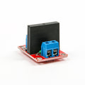
4-Channel 5V Solid State Relay Module (High-Level Trigger) for Arduino, Raspberry Pi & ESP32Default Title · $10.99 · In stock
Overview
This 4-channel solid state relay module switches four independent AC loads with no moving parts. Each channel is an Omron G3MB-202P solid state relay: an opto-triac device that couples your logic signal to the AC side through light, switching 24–240 V AC at up to 2 A per channel. No coil, no click, no contact wear — and switching happens at the AC zero-crossing, which keeps electrical noise remarkably low.
The module is high-level trigger: drive a channel input HIGH and that channel’s SSR conducts, with an LED confirming the state. Inputs arrive twice — a pin header and a duplicate screw-terminal block — and each channel’s AC path runs through its own replaceable 2 A fuse. Power the logic side with 4–6 V on DC+/DC− and the four channel pins connect directly to microcontroller GPIOs.
One boundary to respect before wiring anything: solid state relays of this type switch AC only — a triac never turns off on DC — and 2 A is a real ceiling, not a suggestion. Within those limits it is the clean, silent way to switch lamps, fans, pumps, and heaters. This manual covers the pinout, wiring for four platforms, code, and the SSR-specific questions that surprise people.
At a Glance
Channels
4 × Omron G3MB-202P SSR
Trigger
Active HIGH per channel
Switches
24 – 240 V AC only
Load Limit
2 A per channel (fused)
Logic Supply
4 – 6 V on DC+ / DC−
Switching
Zero-crossing, silent
Specifications
Parameter
Value
Relays
4 × Omron G3MB-202P
Load voltage
24 – 240 V AC, 50/60 Hz
Load current
2 A max per channel (resistive)
Protection
Replaceable 2 A fuse per channel
Trigger logic
High level — HIGH = ON
Trigger current
A few mA per channel; 3.3 V and 5 V GPIOs both work
Logic supply
4 – 6 V DC on DC+ / DC−
Switching type
Zero-crossing triac output
Isolation
Opto-isolated input-to-output inside each SSR
Indicators
Status LED per channel
Inputs
Pin header + duplicate screw terminals
DC loads
Not supported — AC only
Pinout Diagram
Left side: the control inputs — DC+ (4–6 V), DC− (ground), and CH1–CH4, available on both the header and the screw-terminal block. Right side: four 2-position AC output terminals, one per channel, each in series with its green 2 A fuse. The channel LEDs sit beside the input header.
Wiring Guide
Arduino Uno Wiring
Module Pin
Arduino Uno Pin
Notes
DC+
5V
Logic-side power
DC−
GND
Common ground
CH1 / CH2 / CH3 / CH4
D4 / D5 / D6 / D7
HIGH = channel ON
AC outputs
In series with each load’s live wire
One load per channel, 2 A max
Mains kills. The AC terminals carry line voltage. Wire loads with the circuit de-energized, put the module in an enclosure so no AC terminal is touchable, strain-relieve the cables, and never work on the AC side while it is plugged in. If mains wiring is new to you, have someone qualified check your work.
ESP32 Wiring
Module Pin
ESP32 Pin
Notes
DC+
VIN (5V)
Logic-side power
DC−
GND
Common ground
CH1–CH4
GPIO 25 / 26 / 27 / 33
3.3 V HIGH triggers reliably
Boot-state matters. Some ESP32 pins pulse at boot (GPIO 0, 2, 12, 15) — on a high-trigger board that pulse flashes your loads. The pins above stay quiet during reset, so relays remain off until your code says otherwise.
Raspberry Pi Wiring
Module Pin
Raspberry Pi Pin
Notes
DC+
5V (Pin 2)
Logic-side power
DC−
GND (Pin 6)
Common ground
CH1–CH4
GPIO 17 / 27 / 22 / 23
3.3 V HIGH = ON
Why SSRs suit the Pi. No coil means no back-EMF spikes and only a few milliamps per channel — gentle on the Pi’s GPIO and power budget, with none of the mechanical relay chatter that can reset a marginal supply.
Raspberry Pi Pico Wiring
Module Pin
Pico Pin
Notes
DC+
VBUS (Pin 40)
5 V from USB
DC−
GND (Pin 38)
Common ground
CH1–CH4
GP2 / GP3 / GP4 / GP5
HIGH = ON
AC only, 2 A only. These SSRs cannot switch DC (the triac latches on), and 2 A means ~450 W at 230 V or ~220 W at 110 V per channel — lamps, fans, small pumps, solenoid valves. Space heaters, kettles, and motors with big inrush belong on a heavier relay.
Code Examples
Arduino — Four-Channel Sequencer
ssr4_sequence.ino
const int CH[4] = {4, 5, 6, 7};

void setup() {
  for (int i = 0; i < 4; i++) {
    pinMode(CH[i], OUTPUT);
    digitalWrite(CH[i], LOW);   // all off at boot
  }
}

void loop() {
  for (int i = 0; i < 4; i++) {
    digitalWrite(CH[i], HIGH);  // ON
    delay(1000);
    digitalWrite(CH[i], LOW);   // OFF
  }
}
ESP32 — Timed Channel Control
esp32_ssr4.ino
const int CH[4] = {25, 26, 27, 33};

void setup() {
  Serial.begin(115200);
  for (int i = 0; i < 4; i++) {
    pinMode(CH[i], OUTPUT);
    digitalWrite(CH[i], LOW);
  }
}

void loop() {
  // channel 1 on a 10 s cycle, channel 2 opposite phase
  bool phase = (millis() / 10000) % 2;
  digitalWrite(CH[0], phase);
  digitalWrite(CH[1], !phase);
  Serial.printf("CH1=%d CH2=%d\n", phase, !phase);
  delay(500);
}
Raspberry Pi — Python (gpiozero)
ssr4_control.py
from gpiozero import DigitalOutputDevice
from time import sleep

# active_high=True: HIGH turns the channel on
channels = [DigitalOutputDevice(pin, active_high=True, initial_value=False)
            for pin in (17, 27, 22, 23)]

try:
    while True:
        for i, ch in enumerate(channels, start=1):
            ch.on()
            print(f"Channel {i} ON")
            sleep(1)
            ch.off()
except KeyboardInterrupt:
    for ch in channels:
        ch.off()
Raspberry Pi Pico — MicroPython
pico_ssr4.py
from machine import Pin
import time

channels = [Pin(n, Pin.OUT, value=0) for n in (2, 3, 4, 5)]

while True:
    # all on together, then off one by one
    for ch in channels:
        ch.value(1)
    time.sleep(2)
    for ch in channels:
        ch.value(0)
        time.sleep(0.5)
Frequently Asked Questions
Why does my DC load stay on forever?
Because the output device is a triac: it turns off only when the load current crosses zero, which AC does 100–120 times a second and DC never does. Once triggered on DC, the channel latches until you cut the supply. For DC loads use a MOSFET module or a mechanical relay instead.
My LED bulb glows faintly or flickers when the channel is off. Why?
SSRs leak a small current (and their snubber network passes a little more) even when off. Incandescent loads never notice, but a few-watt LED bulb can glow or blink with it. Fixes: a small load-side snubber/bleeder resistor, a slightly larger LED load, or a mechanical relay for that circuit.
Can I dim lights with PWM on the channel pins?
No. Zero-crossing SSRs can only switch whole half-cycles, so fast PWM just produces erratic flicker. They are on/off devices. Dimming AC requires a phase-control dimmer module (random-fire triac with zero-cross detection) — a different product.
Will 3.3 V GPIOs trigger it reliably?
Yes. Each input needs only a few milliamps, and 3.3 V comfortably exceeds the transistor drive threshold on this board with DC+ at 5 V. All four examples above run the inputs straight from 3.3 V pins (ESP32, Pi, Pico) without help.
Does it need a heatsink at 2 A?
No — the G3MB-202P is rated 2 A without one, and warm-to-the-touch operation near full load is normal. What it does need is airflow: four channels at 2 A each in a sealed box adds up, so ventilate the enclosure and derate to ~1.5 A per channel in hot environments.
Is the microcontroller isolated from the mains?
The isolation barrier is inside each SSR, between its input LED and its triac output — the AC side never touches the logic side. Your microcontroller shares ground with the module’s DC input side only. That isolation holds as long as the wiring keeps AC strictly on the output terminals.
A channel stopped switching. Fuse or relay?
Check the fuse first: with power removed, meter it for continuity — the green axial fuses pop exactly when an overload or inrush spike exceeds 2 A. If the fuse is fine but the LED lights without the load switching, the SSR itself has likely failed; they are through-hole parts and can be replaced with a soldering iron.
Reference documents for the 4-Channel 5V Solid State Relay Module (High-Level Trigger) for Arduino, Raspberry Pi & ESP32. This manual covers wiring and code; the documents below carry the full electrical specifications.