1.3" 240x240 IPS TFT LCD Display Module (ST7789, 7-Pin) for Arduino, ESP32 & STM32Default Title · $8.99 · In stock
Overview
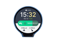
This 1.3″ TFT display packs a 240×240 IPS panel driven by the ST7789 controller into a module barely bigger than a postage stamp. IPS is the key word: unlike the washed-out TN panels on older hobby displays, colors stay vivid and readable from practically any angle, with deep contrast and 65K colors. For gauges, dashboards, thumbnails, and small game screens it is one of the best value displays in the hobby.
The 7-pin header keeps wiring lean: SPI clock (SCL) and data (SDA, which is SPI MOSI — the I2C-style names mislead), a reset line, the data/command line every SPI display needs, and a backlight control pin. What is missing is deliberate: this variant has no CS pin. The chip-select is tied active internally, which saves a wire but means the display permanently owns its SPI bus and wants SPI mode 3 — both handled in the code below.
The module is a 3.3 V device, power and logic, which makes ESP32, Raspberry Pi, and Pico direct connections. This manual covers the pinout, wiring for all four platforms (including the safe way to drive it from a 5 V Arduino), first-pixels code for each, and the usual questions about the missing CS pin, offsets, and backlight dimming.
At a Glance
Panel
1.3″ IPS, 240 × 240
Controller
ST7789 (SPI)
Colors
65K (RGB565)
Supply / Logic
3.3 V
Pins
7 — no CS (tied internally)
Backlight
BLK pin, PWM dimmable
Specifications
Parameter
Value
Display
1.3″ IPS TFT, 240 × 240 pixels
Controller
Sitronix ST7789
Color depth
16-bit RGB565 (65K colors)
Interface
4-wire SPI (SCL, SDA/MOSI, DC, RES)
Chip select
None — internally tied active; use SPI mode 3
SPI speed
Up to ~40 MHz (higher often works)
Supply voltage
3.3 V
Logic level
3.3 V (level-shift from 5 V boards)
Backlight
BLK pin, high = on, PWM dimmable
Viewing angle
~170° (IPS)
Header
7-pin: GND · VCC · SCL · SDA · RES · DC · BLK
Pinout Diagram
Seven pins on the right edge. Note the naming trap: SCL is the SPI clock and SDA is SPI MOSI — this is not an I2C display. BLK is the backlight enable; leave it unconnected (it is pulled on) or drive it with PWM to dim.
Wiring Guide
Arduino Uno Wiring
Display Pin
Arduino Uno Pin
Notes
GND
GND
Common ground
VCC
3.3V
Not 5 V
SCL
D13 (SCK)
Through a level shifter
SDA
D11 (MOSI)
Through a level shifter
RES
D8
Through a level shifter
DC
D9
Through a level shifter
BLK
Unconnected
Backlight defaults on
The Uno is a 5 V board; the display is not. Use a level shifter (or at minimum ~1–2 kΩ series resistors) on SCL, SDA, RES, and DC. Boards driven directly from 5 V logic often work for a while — and then stop. ESP32 and Pico avoid the problem entirely.
ESP32 Wiring
Display Pin
ESP32 Pin
Notes
GND
GND
Common ground
VCC
3V3
Direct
SCL
GPIO 18 (SCK)
VSPI clock
SDA
GPIO 23 (MOSI)
VSPI data
RES
GPIO 17
Any free GPIO
DC
GPIO 16
Any free GPIO
BLK
GPIO 4 (optional)
PWM for brightness
Crank the SPI clock. The ESP32 drives this panel happily at 40 MHz+, which is the difference between visible redraws and fluid animation. Set it with tft.setSPISpeed(40000000) after init.
Raspberry Pi Wiring
Display Pin
Raspberry Pi Pin
Notes
GND
GND (Pin 6)
Common ground
VCC
3.3V (Pin 1)
Direct
SCL
GPIO 11 / SCLK (Pin 23)
SPI0 clock
SDA
GPIO 10 / MOSI (Pin 19)
SPI0 data
RES
GPIO 25 (Pin 22)
Reset
DC
GPIO 24 (Pin 18)
Data/command
BLK
GPIO 18 (Pin 12, optional)
PWM backlight
Enable SPI:sudo raspi-config → Interface Options → SPI. The Python code below pushes full frames from PIL images, so anything you can draw with Pillow — text, charts, photos — lands on the panel.
Raspberry Pi Pico Wiring
Display Pin
Pico Pin
Notes
GND
GND (Pin 38)
Common ground
VCC
3V3(OUT) (Pin 36)
Direct
SCL
GP18 / SPI0 SCK (Pin 24)
Clock
SDA
GP19 / SPI0 TX (Pin 25)
MOSI
RES
GP20 (Pin 26)
Reset
DC
GP21 (Pin 27)
Data/command
BLK
Unconnected
Or any GPIO for dimming
Driver file: copy the pure-MicroPython st7789py.py driver to the board. It is not the fastest way to drive the panel (the C module is), but it needs no custom firmware and is perfect for text and gauges.
There is none — chip select is tied active inside the module. Two consequences: pass -1 (or None) as the CS pin in libraries, and initialize with SPI mode 3, because with CS permanently low the ST7789 samples the clock differently. The code examples above do both.
Can it share an SPI bus with other devices?
Not comfortably. With no CS the display listens to everything on the bus, so traffic meant for an SD card or a second display corrupts the screen. Give it its own SPI peripheral (the ESP32 and Pico both have two) or choose the 8-pin ST7789 variant that includes CS when bus sharing matters.
Can I power it from 5 V?
No — this 7-pin module expects 3.3 V on VCC and 3.3 V logic. On a 5 V Arduino, power it from the 3.3 V pin and level-shift the four signal lines. Getting away with direct 5 V wiring is common and also the most common way these panels die early.
How do I dim the backlight?
Drive BLK with PWM: full high is full brightness, and duty cycle scales it down smoothly. Left unconnected, the pin is pulled high and the backlight is simply always on. Turning BLK off is also the correct “screen off” power saving, since the panel itself draws little.
My image is shifted or has a band of noise pixels. Why?
The ST7789 addresses a 240×320 memory; a 240×240 panel uses a window of it with an 80-pixel offset. Libraries handle this when told the right size — tft.init(240, 240) or the width/height arguments in the Python drivers. Wrong size or rotation settings are what produce the shifted image or the noisy stripe.
Is it sunlight readable / how good is IPS here?
Indoors it is excellent — wide angles, strong contrast, vivid color. In direct sunlight it washes out like most transmissive LCDs. For outdoor gadgets pair it with a shade or bump the backlight to full; for pure sunlight readability an e-paper panel is the better tool.
How fast can I refresh it?
Full-frame redraws are governed by SPI speed: a 240×240 RGB565 frame is 115 KB, so at 40 MHz you can theoretically push ~40 fps. In practice the Adafruit/ESP32 combination manages fluid gauges and simple animation easily; the pure-Python Pico driver is best treated as a static-content display.
Reference documents for the 1.3" 240x240 IPS TFT LCD Display Module (ST7789, 7-Pin) for Arduino, ESP32 & STM32. This manual covers wiring and code; the documents below carry the full electrical specifications.