

Video Tutorial (Optional)
Watch first if you want to follow the full build in real time.
Project Overview
Raspberry Pi Pico + HC-SR501 PIR sensor: In this project, you connect an HC-SR501 (HCSR501) PIR motion sensor to a Raspberry Pi Pico (or Pico W) and trigger an LED when motion is detected.
The HC-SR501 is a low-cost and reliable way to detect motion using infrared changes in its surroundings, which makes it useful for home automation and security-style builds.
- Time: 20 to 40 minutes
- Skill level: Beginner
- What you will build: A motion-detected LED indicator using a Raspberry Pi Pico and an HC-SR501 PIR sensor
Parts List
From ShillehTek
- ShillehTek HCSR501 PIR Sensor - detects motion and outputs a digital HIGH/LOW signal
- ShillehTek Breadboard - solderless wiring for the Pico and modules
- Jumper wires - makes the connections between Pico, PIR sensor, and LED
- Raspberry Pi Pico 2W - the microcontroller board used in this build
External
- LED (any color) - visual indicator when motion is detected
- 220Ω resistor - current limiting for the LED
- USB cable - to program the Pico
Note: The HC-SR501 is typically rated for 5V VCC, but many modules include an onboard regulator and will still work at 3.3V. Running at 3.3V may reduce range or signal stability depending on the specific module.
Step-by-Step Guide
Step 1 - Wire the HC-SR501 PIR sensor and LED to the Pico
Goal: Connect the PIR sensor output to a GPIO input and wire an LED to a GPIO output.
What to do: Use the HC-SR501 pins VCC, GND, and OUT:
- HC-SR501 VCC to Pico 3.3V (Pin 36)
- HC-SR501 GND to Pico GND (Pin 38)
- HC-SR501 OUT to Pico GPIO 0
Wire the LED (with a series resistor):
- LED anode (long leg) to GPIO 2 (Pin 4) through a 220Ω resistor
- LED cathode (short leg) to GND (Pin 38)
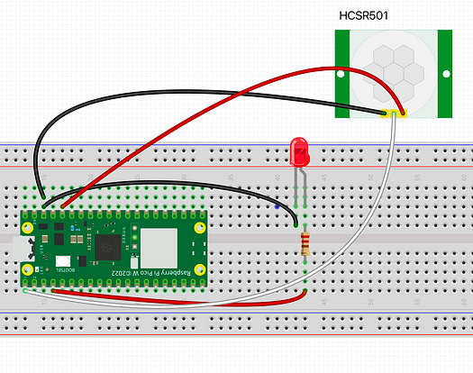
Expected result: The PIR sensor is powered and its OUT pin is connected to GPIO0, and the LED is connected to GPIO2 through a 220Ω resistor.
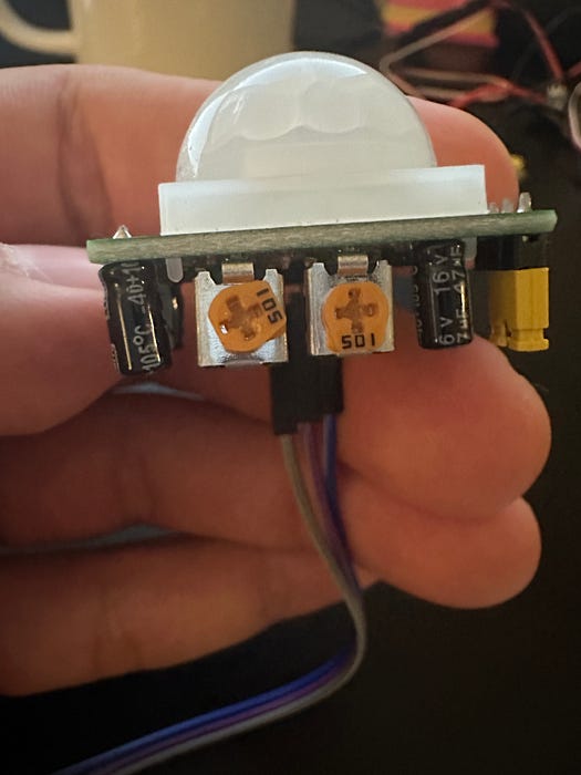
Step 2 - Set time delay, sensitivity, and trigger mode on the HC-SR501
Goal: Configure the HC-SR501 so motion events reset quickly and behave consistently.
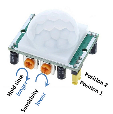
What to do: Adjust the two onboard potentiometers:
- Time delay (left potentiometer): set fully counter-clockwise for the shortest delay (about 0.3 seconds).
- Sensitivity (right potentiometer): set to the middle position for a moderate detection range.
For this project, set the module to the low position (position 1 in the diagram) so the output does not repeat HIGH until the time delay is exhausted. If left in the high position, repeat triggering can keep the output HIGH beyond the time delay setting.
Expected result: Motion causes the sensor to go HIGH briefly, then return LOW after a short delay, without staying HIGH for an extended time.
Step 3 - Upload the MicroPython motion detection code
Goal: Read GPIO0 from the PIR sensor and turn the LED on GPIO2 on and off using a 3-second debounce window.
What to do: Copy this code to your Pico (for example as main.py) and run it in MicroPython.
Code:
from machine import Pin
import time

# Initialize PIR sensor on GPIO 0
pir = Pin(0, Pin.IN, Pin.PULL_DOWN)
led = Pin(2, Pin.OUT)  # Initialize LED on GPIO 2
pir_state = False  # Start assuming no motion detected
last_motion_time = 0  # Timestamp of the last motion detected
debounce_time = 3  # Debounce period in seconds

print("PIR Module Initialized")
time.sleep(1)  # Allow the sensor to stabilize
print("Ready")

while True:
    val = pir.value()  # Read input value from PIR sensor
    current_time = time.time()

    if val == 1:  # Motion detected
        if not pir_state and (current_time - last_motion_time >= debounce_time):
            print(current_time - last_motion_time)
            print("Motion detected!")
            pir_state = True
            led.on()  # Turn on LED
            last_motion_time = current_time  # Update the last motion timestamp

    elif val == 0:
        if pir_state and (current_time - last_motion_time >= debounce_time):
            pir_state = False
            led.off()
            last_motion_time = current_time  # Update the last motion timestamp

    time.sleep(0.1)  # Small delay to prevent spamming
Expected result: When motion is detected, the serial console prints a message and the LED turns on. After motion ends and the debounce time has passed, the LED turns off.
Step 4 - Verify motion detection and LED behavior
Goal: Confirm the sensor output, debounce behavior, and LED indicator are working as intended.
What to do: Wave a hand in front of the sensor and watch the LED and serial console output.
Expected result: The LED lights when motion is detected and turns off after motion ends, with a 3-second debounce period preventing rapid toggling.
Conclusion
You built a motion-triggered LED indicator using a Raspberry Pi Pico (or Pico W) and an HC-SR501 (HCSR501) PIR sensor. The Pico reads the PIR digital output on GPIO0 and drives an LED on GPIO2, with a debounce delay to keep the behavior stable.
Want the exact parts used in this build? Grab them from ShillehTek.com. If you want help customizing this project or building something similar for your product, check out our IoT consulting services.
You can also follow along on YouTube and browse the ShillehTek Amazon Store.


.png?v=25000753014097803521779072085)

.png?v=68677308723310773341779072085)


