

Project Overview
Arduino Nano + MQ-7 CO Sensor: Read carbon monoxide levels on an analog pin, visualize spikes in the Serial Plotter, then turn the readings into a buzzer alarm when air quality gets worse.
- Time: ~45 minutes
- Skill level: Beginner
- What you will build: A three-wire CO monitor on an Arduino Nano, plus an optional temperature + buzzer alarm upgrade.

Safety note: A DIY sensor is a great learning tool and trend monitor, but it is not a certified life-safety device. Keep a UL-listed CO alarm where people sleep.
Parts List
From ShillehTek
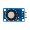
- MQ-7 Carbon Monoxide (CO) Gas Sensor Module - carrier board with load resistor built in
- Arduino Nano V3.0 Pre-Soldered - Uno works identically
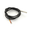
- DS18B20 Waterproof Temperature Probe - for the practical alarm example
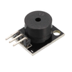
- KY-006 Passive Piezo Buzzer - the alarm sound
- 400-Point Breadboard
- Dupont Jumper Wires
External
- None - though a 10 kΩ resistor is worth knowing about if you ever use a bare MQ-7 without a carrier board
Note: The original build soldered a bare MQ-7 onto a Pololu carrier with a 10 kΩ load resistor. The ShillehTek module has the carrier circuitry (load resistor, indicator LEDs, and both analog and digital outputs) already on board, so you skip the soldering entirely.
Step-by-Step Guide
Step 1 - Prepare the Sensor
Goal: Get the MQ-7 electrically ready.
What to do: On a bare sensor, you would solder it to a carrier PCB with a 10 kΩ load resistor. Orientation does not matter because the pinout is symmetric with no polarity. With the ready-made module, inspect the pins: VCC, GND, A0 (analog out), and D0 (digital threshold out).

Expected result: A sensor with clean 3-wire access: power, ground, analog signal.
Step 2 - Wire It (3 Wires)
Goal: Connect the sensor output to the Arduino ADC.
What to do: VCC to 5V, GND to GND, A0 to A0. That is the whole circuit. The heater inside the sensor draws real current, so power from USB or a solid 5V rail.

Expected result: Sensor powered and warming up (this is normal and necessary).
Step 3 - Read It with AnalogReadSerial
Goal: Stream raw CO readings over Serial.
What to do: The stock Arduino example is enough to start:
// AnalogReadSerial - reads A0 and prints to Serial
// (File  Examples  01.Basics  AnalogReadSerial)

void setup() {
  Serial.begin(9600);
}

void loop() {
  int sensorValue = analogRead(A0);
  Serial.println(sensorValue);
  delay(100);
}
Open the Serial Monitor and let the sensor warm up for a few minutes. Values settle as the heater reaches temperature.

Expected result: A steady baseline number that reflects clean air.
Step 4 - The Breath Test (Serial Plotter)
Goal: See the sensor respond in real time.
What to do: Switch to Tools to Serial Plotter and breathe gently on the sensor. Exhaled air contains trace CO and changes the element resistance. The plot jumps immediately, then decays back to baseline.

Expected result: Confirmed sensitivity as the sensor reacts to changes in the air within about a second.
Step 5 - Practical Example: CO + Temperature Alarm
Goal: Turn readings into an actual warning device.
What to do: Pair the MQ-7 with a Dallas DS18B20 temperature sensor and a buzzer. When the CO reading crosses a threshold, the buzzer sounds. Set the threshold based on your clean-air baseline plus margin.
#include <OneWire.h>
#include <DallasTemperature.h>

#define CO_PIN     A0
#define BUZZER_PIN 8
#define ONE_WIRE   2
#define CO_LIMIT   400   // pick from YOUR clean-air baseline + margin

OneWire oneWire(ONE_WIRE);
DallasTemperature tempSensor(&oneWire);

void setup() {
  Serial.begin(9600);
  pinMode(BUZZER_PIN, OUTPUT);
  tempSensor.begin();
}

void loop() {
  int co = analogRead(CO_PIN);
  tempSensor.requestTemperatures();
  float tempC = tempSensor.getTempCByIndex(0);

  Serial.print("CO: ");   Serial.print(co);
  Serial.print("  T: ");  Serial.println(tempC);

  if (co > CO_LIMIT) {
    tone(BUZZER_PIN, 1000);   // alarm!
  } else {
    noTone(BUZZER_PIN);
  }
  delay(250);
}
Expected result: A room monitor that sounds when CO rises above your chosen threshold.
Step 6 - Understand the Limits
Goal: Use the readings honestly.
What to do: Raw ADC values are relative, not calibrated ppm. For trends and threshold alarms they work well. For datasheet-accurate CO concentration, the MQ-7 typically uses a cycled heater voltage (5 V / 1.4 V phases) and calibration in known air. Set your alarm threshold from your own clean-air baseline plus a healthy margin.
Expected result: A useful monitor and realistic expectations about what the MQ-7 readings mean.
Conclusion
With an Arduino Nano and an MQ-7 module, you can read live CO values using a simple analog input sketch, then build up to a buzzer alarm by comparing readings against your baseline threshold. Adding a DS18B20 temperature probe is an easy upgrade for richer room monitoring.
Want the exact parts used in this build? Grab them from ShillehTek.com. If you want help customizing this project or building something for your product, check out our IoT consulting services.
Credits
All photos and images in this tutorial are credited to Ingo Lohs on Hackster.io. The original guide by Ingo Lohs served as the reference for this ShillehTek version. We thank him for his excellent work in the maker community.





.png?v=25000753014097803521790455663)

.png?v=68677308723310773341790455663)


