RC Servo Tester & CCPM Consistency CheckerDefault Title · $7.99 · In stock
Overview
The RC Servo Tester (also sold as the CCPM Consistency Master) is a small standalone tool that generates the standard RC servo signal — a 50 Hz PWM pulse train — without needing a receiver, flight controller, or any code. Plug in a servo, feed it 4.8–6 V, and turn the knob: the servo follows. It is the fastest way to answer the eternal bench questions: is this servo alive, how far does it travel, and does it center properly?
Three output columns carry the same signal simultaneously, which is where the “CCPM consistency” name comes from: helicopter swashplates driven by three servos need all three to respond identically, and driving them side by side instantly exposes a slow or off-center unit. The three modes cover the practical cases — Manual puts the pulse width on the knob, Neutral locks the output at the 1.5 ms center point for installing servo horns, and Auto sweeps back and forth continuously for endurance and smoothness checks.
It also doubles as an ESC tester: an electronic speed controller reads the same signal as a servo, so the tester works as a stand-in throttle for bench-testing and calibrating ESCs. This manual covers the pinout, the wiring for servos, multi-servo comparison, and ESCs, the three modes, and microcontroller sketches that measure or reproduce what the tester does.
At a Glance
Function
Standalone servo & ESC tester
Outputs
3 channels, S / + / − each
Power Input
4.8 – 6 V DC
Modes
Manual · Neutral · Auto sweep
Signal
50 Hz PWM, ~0.8–2.2 ms pulse
Compatible
Analog & digital servos, ESCs
Specifications
Parameter
Value
Supply voltage
4.8 – 6 V DC (battery pack, BEC, or bench supply)
Signal format
Standard RC PWM, 50 Hz frame
Pulse range
Approx. 0.8 – 2.2 ms (knob), 1.5 ms in Neutral
Output channels
3, driven with the identical signal
Output header
3 × 3 pins, rows S / + / −
Input header
3-pin column: S · + · −
Modes
Man (knob), Neutral (center), Auto (sweep)
Mode switch
Select button, mode shown by 3 LEDs
Servo types
Analog and digital, standard connectors
ESC testing
Yes — acts as a throttle signal source
Size / weight
Approx. 46 × 42 × 26 mm · ~9 g
Pinout Diagram
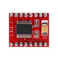
The left header is the OUT side: three identical columns (1–3), each with rows S (signal), + (power), and − (ground) — a servo plug slides straight onto a column. The right 3-pin column is the power input, marked 4.8–6 V, with the same S / + / − ordering. The knob drives Manual mode, the select button cycles modes, and the three LEDs show which mode is active.
Wiring Guide
Basic Setup: One Servo
Connection
Where
Notes
Servo plug
Any OUT column
Signal wire (orange/white) on the S row
Servo red wire
+ row
Power passes through from the input
Servo brown/black wire
− row
Ground
Battery / supply 4.8–6 V
IN column, + and −
4–5 cell NiMH, 5 V BEC, or bench supply
Mind the 6 V ceiling. A 2S LiPo (7.4 V) is too much for the tester and for most servos — run LiPo packs through a 5–6 V BEC/UBEC first. Reversed servo plugs do no harm (the servo just ignores the signal), but reversed supply polarity can kill the tester.
Comparing 3 Servos (CCPM Consistency)
Connection
Where
Notes
Servo 1 / 2 / 3
OUT columns 1 / 2 / 3
All three receive the identical pulse
Supply 4.8–6 V
IN + / −
Budget ~1 A per servo under load
Mode
Auto or Man
Watch for a lagging or off-center unit
How to read the result. In Auto mode all three arms should move as one. A servo that starts late, arrives late, or centers at a different angle is the mismatched one — on a helicopter swashplate that difference becomes a permanent tilt, so match servos from the same model and batch where possible.
Testing an ESC
Connection
Where
Notes
ESC 3-wire lead
Any OUT column
Signal on S; the ESC’s BEC back-feeds + / − and powers the tester
Main battery
ESC power leads
Motor connected, propeller OFF
Opto ESC (no BEC)
Add 5 V to IN + / −
Opto ESCs do not supply power to the tester
Remove the propeller. Every ESC bench test starts with the prop off — no exceptions. For throttle calibration: set Man mode with the knob at maximum, power the ESC, wait for the beeps, then turn the knob to minimum. That teaches the ESC the tester’s full throttle range, exactly like a transmitter would.
What Each Mode Does
Mode
LED
Behavior
Man
Man LED lit
Knob sets the pulse width directly (~0.8–2.2 ms)
Neutral
Neutral LED lit
Output locked at 1.5 ms center — perfect for fitting servo horns straight
Auto
Auto LED lit
Continuous sweep end-to-end for smoothness and endurance checks
Switching
—
Press the select button to cycle modes
Why Neutral matters. Servo arms should be installed with the servo at its true center, not wherever it happened to stop. Neutral holds an exact 1.5 ms signal, so the horn you press on now is the horn that is straight in the finished model.
Code Examples
Arduino — Measure the Tester’s Pulse Width
pulse_meter.ino
// Tester OUT column S pin -> D2, tester GND -> Arduino GND
const int PULSE_PIN = 2;

void setup() {
  Serial.begin(9600);
  pinMode(PULSE_PIN, INPUT);
}

void loop() {
  // Width of the HIGH pulse in microseconds (typ. 800-2200)
  unsigned long us = pulseIn(PULSE_PIN, HIGH, 100000);
  if (us > 0) {
    Serial.print("Pulse: ");
    Serial.print(us);
    Serial.println(" us");
  } else {
    Serial.println("No signal");
  }
  delay(200);
}
Arduino — Build Your Own “Man Mode”
knob_servo.ino
#include <Servo.h>

// Servo signal -> D9, potentiometer wiper -> A0
Servo servo;

void setup() {
  servo.attach(9, 800, 2200);   // match the tester's range
}

void loop() {
  int raw = analogRead(A0);               // 0-1023
  int us = map(raw, 0, 1023, 800, 2200);  // knob -> pulse width
  servo.writeMicroseconds(us);
  delay(15);
}
ESP32 — Auto-Sweep Equivalent
esp32_sweep.ino
// Library Manager: install "ESP32Servo"
#include <ESP32Servo.h>

Servo servo;

void setup() {
  servo.setPeriodHertz(50);
  servo.attach(18, 800, 2200);   // signal on GPIO 18
}

void loop() {
  for (int us = 800; us <= 2200; us += 10) {
    servo.writeMicroseconds(us);
    delay(10);
  }
  for (int us = 2200; us >= 800; us -= 10) {
    servo.writeMicroseconds(us);
    delay(10);
  }
}
Raspberry Pi Pico — MicroPython Servo Driver
pico_servo.py
from machine import Pin, PWM
import time

# Servo signal -> GP15, servo power from 5V (VBUS), common GND
pwm = PWM(Pin(15))
pwm.freq(50)

def write_us(us):
    # 50 Hz frame = 20000 us; duty_u16 is 0-65535
    pwm.duty_u16(int(us * 65535 / 20000))

while True:
    write_us(1500)      # neutral
    time.sleep(1)
    for us in range(800, 2201, 10):   # sweep up
        write_us(us)
        time.sleep(0.01)
    for us in range(2200, 799, -10):  # sweep down
        write_us(us)
        time.sleep(0.01)
Frequently Asked Questions
Which servos does it work with?
Any servo that uses the standard 3-wire RC interface and runs on 4.8–6 V — that covers nearly every analog and digital hobby servo, from 9 g micros to standard-size units. High-voltage (7.4 V+) servos will move on 6 V but only reach full speed and torque on their rated voltage.
Can I power it straight from a 2S LiPo?
No — 2S is 7.4–8.4 V and the tester (and most servos) top out at 6 V. Put a 5–6 V BEC or UBEC between the pack and the tester’s input. A 4- or 5-cell NiMH receiver pack or a USB bench supply at 5 V works directly.
My servo buzzes at the ends of the knob range. Is it broken?
Usually not. The tester’s pulse range (~800–2200 µs) is deliberately wider than many servos’ mechanical travel, so at the extremes the servo pushes against its internal end stops and hums. Back the knob off slightly and the buzz stops. Continuous stalling at the stops does wear a servo, so do not park it there.
How do I calibrate an ESC with it?
Prop off. Select Man mode and turn the knob to maximum, connect the ESC lead to an OUT column, then power the ESC from its battery. After the high-throttle beeps, turn the knob to minimum and wait for the confirmation tones. The ESC has now learned the range — the same procedure you would do with a transmitter.
How many servos can it drive at once?
Three, one per output column. The practical limit is current, not the signal: the servo power flows from your input supply through the tester, so three loaded servos can easily draw 2–3 A. Use a supply that can deliver it and keep the leads short; if servos twitch or the tester resets, the supply is sagging.
The servo does nothing. What should I check?
In order: supply polarity and voltage at the IN pins, the servo plug orientation (signal wire on the S row), whether a mode LED is lit at all, and finally the servo on a second output column. A tester with LEDs on and a known-good servo that still will not move points to a damaged servo lead — wiggle-test it while in Auto mode.
Do I still need one if I have a microcontroller?
A microcontroller can generate the same signal — the code examples above do exactly that. The tester’s value is speed and independence: no laptop, no wiring a breadboard at the flying field, no code to upload. For quick go/no-go checks and horn centering it is simply faster; for automated or scripted testing, use the MCU.
Reference documents for the RC Servo Tester & CCPM Consistency Checker. This manual covers wiring and code; the documents below carry the full electrical specifications.