Overview
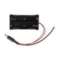
This box holds two 18650 lithium-ion cells under a fitted cover and delivers their power through a lead ending in a 5.5 × 2.1 mm DC barrel plug, with an on/off switch in the circuit. Two cells in series make a 7.4 V pack — enough headroom for an Arduino’s barrel jack, a motor driver, or a buck converter feeding a 5 V board.
The barrel plug is the convenience here: anything with a matching 5.5 × 2.1 mm DC socket can run from the pack without cutting wires. The same convenience is the risk, because nothing stops you plugging 8 V into a 5 V device that happens to use the same socket. Check the voltage a device expects, and check the plug’s polarity with a multimeter, before the first connection.
It is a holder, not a power bank. Charging, cell protection, and voltage regulation are not specified for this box, so the cells must be charged in a proper lithium-ion charger and protected against over-discharge and short circuits by your cells or your circuit.
At a Glance
Specifications
| Parameter | Value |
| Cell format | 2 × 18650 lithium-ion (18 mm × 65 mm nominal) — not included |
| Cell arrangement | Two cells in series (confirm with a meter) |
| Nominal output | About 7.4 V (2 × 3.7 V) |
| Fully charged | About 8.4 V (2 × 4.2 V) |
| Stop discharging at | About 6.0 V (3.0 V per cell) |
| Output connector | DC barrel plug on a lead: 5.5 mm outer, 2.1 mm inner |
| Plug polarity | Not published — verify with a multimeter before use |
| Switch | Built-in on/off switch |
| Enclosure | Battery box with fitted cover |
| Cell fit | Check length and terminal style, especially for protected cells |
| Charging, protection, regulation | Not specified — provide them externally |
| Current rating | Not published |
Wiring Guide
Two checks come before any wiring. With charged cells fitted and the switch on, measure the plug with a multimeter: red probe inside the barrel, black probe on the outer sleeve. A positive reading of roughly 6–8.4 V means the plug is center-positive, which is what most hobby boards expect; a negative reading means it is center-negative and must not go into a center-positive device. Then confirm that the device accepts that voltage.
Arduino Uno (Barrel Jack)
The Uno’s DC jack takes a 5.5 mm plug with a 2.1 mm center hole, center-positive, and Arduino recommends 7–12 V — a close match for this pack.
| Step | What To Do | Notes |
|---|---|---|
| 1. Verify polarity | Confirm with a meter that the plug is center-positive | The Arduino jack requires center-positive |
| 2. Verify voltage | A charged pack reads up to about 8.4 V | Inside Arduino’s 7–12 V range |
| 3. Plug in | Insert the plug into the barrel jack, then switch the box on | The board’s regulator produces 5 V |
| 4. Watch the low end | Below about 7 V the 5 V rail can start to sag | Recharge the cells before the pack reaches 6 V |
ESP32 Dev Boards (Through a Buck Converter)
ESP32 boards have no barrel jack and expect about 5 V on their 5V/VIN pin. Feeding 8 V straight in makes the small onboard linear regulator burn off the difference as heat, so step the pack down first.
| From | To | Notes |
|---|---|---|
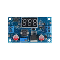
| Pack plug | Buck converter input, through a 5.5 × 2.1 mm socket adapter | Observe polarity at the converter’s IN+ and IN− |
| Buck converter OUT+ (set to 5.0 V) | ESP32 5V / VIN | Adjust the output before connecting the board |
| Buck converter OUT− | ESP32 GND | Common ground |
Raspberry Pi (Through a 5 V Buck Converter)
A Raspberry Pi needs a stable 5 V supply, so the 7.4 V pack must go through a buck converter rated for the Pi’s current. The LM2596 buck converter tutorial walks through setting one up safely.
| From | To | Notes |
|---|---|---|
| Pack plug | Buck converter input | Choose a converter rated for your Pi model’s peak current |
| Buck converter output (set to about 5.1 V) | The Pi’s USB power input, or its 5 V and GND header pins | Set and verify the voltage before connecting the Pi |
| Runtime | Two 18650 cells store roughly 15–25 Wh | A Pi drawing 5 W runs for a few hours at best |
Raspberry Pi Pico (Through a Buck Converter)
The Pico’s VSYS input tops out at 5.5 V, so a 7.4 V pack cannot connect directly.
| From | To | Notes |
|---|---|---|
| Pack plug | Buck converter input | Observe polarity |
| Buck converter OUT+ (set to 5.0 V) | VSYS (pin 39) | Add a series Schottky diode if USB may also be connected |
| Buck converter OUT− | GND (pin 38) | Common ground |