

Project Overview
18650 Battery Capacity Tester: Build an Arduino Nano battery tester that uses a 5V relay module and a power resistor to discharge an 18650 cell, then calculates real capacity in mAh and mWh on a 16x2 LCD.
The number printed on a lithium cell is a promise; the number this tester prints is the truth. It discharges a charged 18650 through a known resistor, reads the voltage every half second, integrates current over time, and cuts the load off with a relay the moment the cell reaches 3.0 V, leaving you with the real milliamp-hours (and milliwatt-hours) on a 16x2 LCD. It is the tool that sorts a bag of salvaged laptop cells into keepers and recyclers.
- Time: ~1 hour (plus 2 to 3 hours per test)
- Skill level: Intermediate
- What you will build: A push-to-start constant-resistance discharge tester with live voltage, current and elapsed time, an automatic low-voltage cutoff, and a final mAh/mWh result.

Parts List
From ShillehTek
- Arduino Nano V3.0 Pre-Soldered - runs the sketch, reads battery voltage, and controls the relay
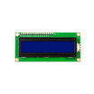
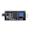
- LCD1602 16x2 Display + PCF8574 I2C Adapter - displays voltage, current, time, and final mAh/mWh
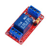
- 1-Channel 5V Relay Module - switches the discharge load on and off for cutoff safety
- Tactile Button Kit - start/reset input
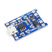
- TP4056 Charger Board - to recharge cells after testing
- 830-Point Breadboard - prototyping the wiring
- Dupont Jumper Wires - quick connections between modules
External
- An 18650 cell holder with leads
- A 4Ω power resistor rated 10 W (or two 8.2Ω 5 W resistors in parallel); it dissipates over 4 W and gets hot
- A multimeter to measure the resistor's real value and your board's 5 V rail
Note: lithium cells are unforgiving. Never discharge below 2.8 V (this tester stops at 3.0 V), never test a swollen, dented or leaking cell, keep the resistor on a ceramic tile away from anything that melts, and never leave the first run unattended. The relay is wired so a dead Arduino means an open circuit.
Step-by-Step Guide
Step 1 - Wire the Discharge Path
Goal: Battery to relay to resistor and back to the battery.
What to do: Battery holder + to relay COM. Relay NO to one end of the 4Ω resistor. Other end of the resistor to battery holder -, and battery - to Arduino GND (shared ground is essential).
Battery + to A0 as well, so the Nano reads the cell voltage directly (a full cell is 4.2 V, safely under the 5 V ADC limit). Relay module: VCC to 5V, GND to GND, IN to D10.

Expected result: With the relay off, nothing flows. With it on, the cell drives about 1 A through the resistor.
Step 2 - Wire LCD and Button
Goal: Readout and a start button.
What to do: I2C LCD: SDA to A4, SCL to A5, VCC to 5V, GND to GND. Button between D9 and GND (internal pull-up).
Expected result: Backlight on, ready for code.
Step 3 - Calibrate Two Numbers
Goal: Improve accuracy by measuring instead of assuming.
What to do: With the multimeter, measure the resistor's actual resistance (a "4Ω" part may read 3.8 to 4.3Ω) and the Nano's 5V pin voltage while powered as it will be during the test (USB 5 V is often 4.8 to 5.1 V). Enter both as R_LOAD and VREF in the sketch. This is the difference between plus or minus 10% and plus or minus 2% results.
Expected result: Two constants that match your hardware.
Step 4 - Upload the Sketch
Goal: Run the discharge test, integrate current over time, and stop automatically at cutoff voltage.
Code:
#include <LiquidCrystal_I2C.h>
LiquidCrystal_I2C lcd(0x27, 16, 2);

const int RELAY = 10, BTN = 9, VBAT = A0;
const bool  RELAY_ON = LOW;      // most 1-channel modules are active-LOW; flip if yours clicks the wrong way
const float VREF     = 5.00;     // measured 5V pin voltage
const float R_LOAD   = 4.0;      // measured load resistance in ohms
const float V_CUTOFF = 3.0;      // stop here (never below 2.8 V)

enum { IDLE, RUNNING, DONE } state = IDLE;
float mAh = 0, mWh = 0;
unsigned long t0, lastStep;

float readV() {                                  // average 32 samples for a steady reading
  long s = 0; for (int i = 0; i < 32; i++) s += analogRead(VBAT);
  return s / 32.0 * VREF / 1023.0;
}

void setup() {
  pinMode(RELAY, OUTPUT); digitalWrite(RELAY, !RELAY_ON);   // load OFF
  pinMode(BTN, INPUT_PULLUP);
  lcd.init(); lcd.backlight();
}

void loop() {
  float v = readV();

  if (state == IDLE) {
    lcd.setCursor(0, 0); lcd.print("Batt "); lcd.print(v, 2); lcd.print("V      ");
    lcd.setCursor(0, 1); lcd.print(v > 3.3 ? "Press to start  " : "Charge battery  ");
    if (digitalRead(BTN) == LOW && v > 3.3) {
      mAh = 0; mWh = 0; t0 = lastStep = millis();
      digitalWrite(RELAY, RELAY_ON);             // load ON
      state = RUNNING; delay(300);
    }

  } else if (state == RUNNING) {
    unsigned long now = millis();
    if (now - lastStep >= 500) {
      float dtH = (now - lastStep) / 3600000.0;  // elapsed hours since last step
      lastStep = now;
      float i = v / R_LOAD;                      // amps through the load
      mAh += i * 1000.0 * dtH;                   // integrate current  -> mAh
      mWh += v * i * 1000.0 * dtH;               // integrate power    -> mWh
      lcd.setCursor(0, 0);
      lcd.print(v, 2); lcd.print("V "); lcd.print(i, 2); lcd.print("A ");
      lcd.print((now - t0) / 60000); lcd.print("m ");
      lcd.setCursor(0, 1);
      lcd.print((int)mAh); lcd.print("mAh "); lcd.print((int)mWh); lcd.print("mWh ");
      if (v <= V_CUTOFF) { digitalWrite(RELAY, !RELAY_ON); state = DONE; }   // load OFF
    }

  } else {                                       // DONE
    lcd.setCursor(0, 0); lcd.print("Done: "); lcd.print((int)mAh); lcd.print(" mAh   ");
    lcd.setCursor(0, 1); lcd.print((int)mWh); lcd.print(" mWh - reset ");
    if (digitalRead(BTN) == LOW) { state = IDLE; delay(300); }
  }
}
What to do: Install LiquidCrystal_I2C, upload, insert a fully charged cell, press the button.
Expected result: The relay clicks, the top line shows something like "4.08V 1.02A 0m", and the mAh count climbs. Two to three hours later the voltage reaches 3.00 V, the relay clicks off, and the LCD shows the capacity, typically 1,800 to 2,800 mAh for a healthy salvaged cell and far less for a tired one.
Step 5 - Read the Result Honestly
Goal: Understand what the capacity number represents.
What to do: Manufacturers rate cells at a gentle 0.2 C discharge down to 2.5 to 2.75 V; our ~1 A load to 3.0 V reads about 5 to 10% lower than the label on a perfect cell. Compare cells against each other with the same rig rather than against the label.
Cells that show under 60% of their rating, get warm, or drop voltage quickly under load are best recycled. Recharge keepers on the TP4056 and mark the measured mAh on the wrapper.
Expected result: A sorted, labeled set of cells you can trust in a pack.
Conclusion
This Arduino Nano relay-based 18650 capacity tester discharges a cell through a known resistor, tracks voltage over time, integrates current, and shuts off at 3.0 V to report real mAh and mWh on a 16x2 LCD. It is a practical way to evaluate and match salvaged cells using a consistent test method.
Want the exact parts used in this build? Grab them from ShillehTek.com. If you want help customizing this project or building something for your product, check out our IoT consulting services.
Photo credit and reference: Mirko Pavleski (mircemk) on Hackster.io.





.png?v=25000753014097803521791168436)

.png?v=68677308723310773341791168436)


