

Project Overview
Arduino Uno + ATmega328P: Use an Arduino Uno as an ISP programmer to burn a bootloader onto a bare ATmega328P so it runs on its internal 8 MHz clock with no crystal, then upload sketches and even rescue or upgrade an Arduino Nano bootloader.
Strip an Uno down to what actually runs your sketch and you're left with one 28-pin chip. On its own, an ATmega328P costs a few dollars, fits in a project box the size of a matchbox and, using its built-in 8 MHz oscillator, needs nothing but power and a decoupling capacitor. The catch is that a new chip arrives blank. This guide turns an Arduino Uno into an in-system programmer (ISP), uses the MiniCore board package to set the chip's fuses and burn a bootloader, and then shows two ways to upload sketches: over serial with a USB-to-TTL cable, or straight through the Uno. The same technique also revives a Nano that won't accept uploads and upgrades old-bootloader clones to the faster, smaller Optiboot.
- Time: ~1 hour
- Skill level: Intermediate
- What you will build: A breadboard Arduino made from a bare ATmega328P running at 8 MHz with no crystal, programmed by an Uno acting as ISP, plus a repaired or upgraded Nano bootloader.

Parts List
From ShillehTek
- Super Starter Kit for Arduino Uno R3 - the Uno that becomes the programmer, plus LEDs, resistors, breadboard and wires
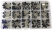
- Electrolytic Capacitor Kit - 10 µF for the Uno's reset, 10 to 100 µF across the chip's supply
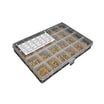
- Ceramic Capacitor Kit - 100 nF decoupling and auto-reset, 22 pF if you add a crystal later
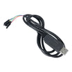
- FT232RL USB-to-TTL Serial Cable - serial uploads and Serial Monitor for the bare chip
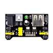
- MB102 Breadboard Power Supply - runs the chip on its own at 5 V or 3.3 V
- Arduino Nano V3.0 - for the rescue/upgrade bonus step
- Dupont Jumper Wires - breadboard wiring between the Uno and the target chip
External
- One or more ATmega328P-PU chips (28-pin DIP)
- Optional: a 16 MHz crystal, if you'd rather build a full-speed Uno-compatible chip
Note: Check the marking on your chip. An ATmega328P and a plain ATmega328 have different signatures, and MiniCore needs to be told which one you have. The DIP package has a notch at one end. Pin 1 is just left of the notch when you look at the chip from above with the notch pointing away from you.
Step-by-Step Guide
Step 1 - Turn the Uno Into a Programmer
Goal: An Uno that speaks the ISP protocol.
What to do: Connect the Uno on its own, open File → Examples → 11.ArduinoISP → ArduinoISP and upload it like any sketch.
Then place a 10 µF capacitor between the Uno's RESET and GND pins (stripe to GND). Without it, opening the serial port to program the target resets the Uno and the programming attempt fails.
Optionally add LEDs with resistors on D9 (heartbeat), D8 (error) and D7 (programming). The ArduinoISP sketch drives all three.
Expected result: With the heartbeat LED fitted, it slowly breathes on and off. The Uno is now a programmer.
Step 2 - Wire the ATmega328P
Goal: Connect the Uno (running ArduinoISP) to the bare ATmega328P for bootloader burning.
What to do: Seat the chip across the middle gap of the breadboard and wire it as shown below.
// Uno running ArduinoISP   ->  ATmega328P-PU (DIP-28)
// D13 (SCK)                ->  pin 19  (SCK)
// D12 (MISO)               ->  pin 18  (MISO)
// D11 (MOSI)               ->  pin 17  (MOSI)
// D10                      ->  pin 1   (RESET)   + 10 kOhm from pin 1 to 5V
// 5V                       ->  pins 7 (VCC) and 20 (AVCC)
// GND                      ->  pins 8 and 22 (GND)
// 100 nF ceramic capacitor directly across pins 7 and 8
// Test LED: pin 19 -> 330 Ohm -> LED -> GND   (pin 19 is Arduino D13)
The 10 kΩ pull-up keeps the chip running when the programmer lets go of RESET, and the 100 nF capacitor right at the power pins stops the supply noise that causes most flaky stand-alone builds. No crystal is needed because you will use the internal oscillator.
Expected result: Six wires from the Uno, two power pairs and a few small parts around the chip.
Step 3 - Install MiniCore and Burn the Bootloader
Goal: Fuses set for the internal 8 MHz clock and a serial bootloader on the chip.
What to do: In File → Preferences add https://mcudude.github.io/MiniCore/package_MCUdude_MiniCore_index.json to the additional boards URLs, then install MiniCore from the Boards Manager.
Select Tools → Board → MiniCore → ATmega328, then set Clock to Internal 8 MHz, Variant to 328P / 328PA (or 328 / 328A for a non-P chip), BOD to 2.7V and Bootloader to Yes (UART0).
Choose the Uno's port, set Tools → Programmer to Arduino as ISP and click Tools → Burn Bootloader.
Expected result: A few seconds of blinking on the Uno's LEDs and "Done burning bootloader". A brand-new chip ships running at 1 MHz, which is why ArduinoISP talks to it slowly. Burning the bootloader also sets the fuses that switch it to 8 MHz. "Invalid device signature" almost always means a wiring or power problem, or the wrong Variant setting.
Step 4 - Upload Sketches
Goal: Get a test sketch onto the stand-alone ATmega328P either via serial or via ISP.
What to do: Use the example sketch below, then pick one upload method.
// Blink + serial check for the stand-alone ATmega328P
void setup() {
  pinMode(13, OUTPUT);                 // Arduino D13 = physical pin 19
  Serial.begin(9600);
}

void loop() {
  digitalWrite(13, HIGH);
  delay(500);
  digitalWrite(13, LOW);
  delay(500);
  Serial.print("Alive at ");
  Serial.print(F_CPU / 1000000);       // prints 8 on the internal oscillator
  Serial.println(" MHz, no crystal");
}
Option A - serial, like a real Arduino: Connect the FT232RL cable's GND to GND, VCC to the 5V rail, TXD to pin 2 (the chip's RXD), RXD to pin 3 (TXD), and the RTS line (green on most FTDI-style cables, check your cable's label) through a 100 nF capacitor to pin 1, keeping the 10 kΩ pull-up. Select the cable's port and click Upload. The RTS pulse resets the chip into its bootloader, like an Uno's auto-reset.
Option B - through the Uno: Leave the ISP wiring in place and use Sketch → Upload Using Programmer. That writes the sketch over the bootloader, so burn the bootloader again later if you want serial uploads back.
Expected result: The LED blinks once a second and, with the FT232RL cable connected, the Serial Monitor at 9600 baud prints "Alive at 8 MHz, no crystal".
Step 5 - Run It on Its Own
Goal: A micro-sized Arduino in your project.
What to do: Disconnect the programmer and power the chip from the MB102 breadboard supply at 5 V or 3.3 V. At 8 MHz it runs anywhere from 2.7 V (the brown-out level you chose) to 5.5 V, so a pair of AA cells or a single LiPo also works.
Arduino pin numbers map to the chip like this: D0/D1 = pins 2/3, D2 to D7 = pins 4 to 6 and 11 to 13, D8 to D13 = pins 14 to 19, A0 to A5 = pins 23 to 28.
For permanent builds, solder a 28-pin DIP socket so the chip can be lifted out and reprogrammed.
One limitation: the internal oscillator is far less precise than a crystal, typically within a percent or two at room temperature, drifting with temperature and voltage. This is fine for sensors, serial and servos, but a clock should take its time from a DS3231 RTC.
Expected result: The same sketch running on a bare chip, a battery and a handful of parts.
Step 6 - Bonus: Rescue or Upgrade a Nano
Goal: Fix "not in sync" upload errors for good.
What to do: Many Nano clones ship with the old bootloader, which uploads at 57600 baud and uses 2 KB of flash. Others get their bootloader damaged.
With the Uno still running ArduinoISP (10 µF on its reset), wire Uno D10 → Nano RST, D11 → D11, D12 → D12, D13 → D13, 5V → 5V and GND → GND.
Select Tools → Board → Arduino Nano, Processor ATmega328P, Programmer Arduino as ISP, and click Burn Bootloader. That writes the modern Optiboot bootloader. From now on choose the plain ATmega328P processor (not "Old Bootloader") and use 115200-baud uploads with 1.5 KB of extra program space.
Expected result: A Nano that uploads reliably with the default settings.
Conclusion
With an Arduino Uno running ArduinoISP and the MiniCore package, a blank ATmega328P becomes a full Arduino in a 28-pin package: fuses set for its internal 8 MHz oscillator and a bootloader for serial uploads through an FT232RL cable. You can also use the same setup to revive misbehaving Nanos and upgrade them to Optiboot.
Want the exact parts used in this build? Grab them from ShillehTek.com. If you want help customizing this project or building something for your product, check out our IoT consulting services.
Credits
All photos and images in this tutorial are credited to Tom Heylen on Hackster.io (LGPL license). The original guide by Tom Heylen served as the reference for this ShillehTek version. We thank them for their excellent work in the maker community.





.png?v=25000753014097803521791168436)

.png?v=68677308723310773341791168436)


