

Project Overview
Arduino Nano GPS speedometer with a NEO-6M GPS module and SSD1306 OLED: the GPS provides ground speed (plus latitude and longitude) and the OLED shows it in large digits for an easy-to-read bike, motorcycle, or car speed display.
The build uses an Arduino Nano with a small battery system so everything fits in a compact enclosure or handlebar mount. Speed readings are typically accurate to within about b11 km/h once the GPS has a solid lock.
- Time: ~1.5 hours
- Skill level: Beginner / Intermediate
- What you will build: A self-contained GPS speedometer with an OLED readout for bike, motorcycle, or car use.

Parts List
From ShillehTek
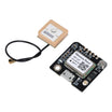
- GT-U7 NEO-6M GPS Module (Pre-Soldered) - GPS receiver for speed, location, and satellite data.
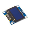
- 0.96" I b2C SSD1306 OLED - compact display for large, readable speed digits.
- Arduino Nano V3.0 Pre-Soldered - main controller to parse GPS data and drive the OLED.
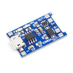
- TP4056 LiPo Charger - charges a single 18650 cell and provides protection.
- MT3608 Boost Converter - boosts battery voltage up to a steady 5.0V.
- 120 PCS Dupont Jumper Wires - quick connections for prototyping and testing.
External
- 18650 LiPo cell
- Small enclosure + handlebar mount (3D-printed or off-the-shelf)
- Open sky for GPS lock (will not work indoors)
Note: First GPS lock typically takes 1 to 5 minutes outdoors. After that, fixes are often around 10 seconds due to on-board RTC and stored almanac data.
Step-by-Step Guide
Step 1 - Inspect the modules
Goal: Confirm you have the right boards and identify the pins you will use.
What to do: Lay out the Arduino Nano, NEO-6M GPS module, and SSD1306 I b2C OLED. Check the GPS pins (VCC, GND, RX, TX) and the OLED pins (VCC, GND, SDA, SCL).


Expected result: You can clearly identify the GPS UART pins and the OLED I b2C pins before connecting anything.
Step 2 - Wire it
Goal: Connect the GPS over SoftwareSerial and the OLED over I b2C, then plan the 5V power path.
What to do: Wire the modules to the Arduino Nano as listed below. Double-check that GPS TX goes to the Arduino receive pin, and GPS RX goes to the Arduino transmit pin.

- NEO-6M VCC 02192 5V, GND 02192 GND, TX 02192 Arduino D4 (RX), RX 02192 Arduino D3 (TX)
- OLED VCC 02192 5V, GND 02192 GND, SDA 02192 A4, SCL 02192 A5
- Power: TP4056 02192 18650 02192 MT3608 (set to 5.0V) 02192 Arduino Vin
Expected result: All modules share a common ground, the OLED is on A4/A5, and the GPS UART is on D4/D3 with correct TX/RX direction.
Step 3 - Install libraries and upload the sketch
Goal: Load firmware that reads GPS speed and displays it on the SSD1306 OLED.
What to do: In the Arduino IDE, install these libraries using Library Manager: TinyGPS++ by Mikal Hart, Adafruit SSD1306, and Adafruit GFX. Then upload the sketch below to your Arduino Nano.

Code:
#include <TinyGPS++.h>
#include <SoftwareSerial.h>
#include <Wire.h>
#include <Adafruit_GFX.h>
#include <Adafruit_SSD1306.h>

SoftwareSerial gpsSerial(4, 3);
TinyGPSPlus gps;
Adafruit_SSD1306 oled(128, 64, &Wire, -1);

void setup() {
  Serial.begin(9600); gpsSerial.begin(9600);
  oled.begin(SSD1306_SWITCHCAPVCC, 0x3C);
  oled.setTextColor(SSD1306_WHITE);
}
void loop() {
  while (gpsSerial.available()) gps.encode(gpsSerial.read());

  oled.clearDisplay();
  if (gps.location.isValid() && gps.speed.isValid()) {
    float kmh = gps.speed.kmph();
    oled.setTextSize(4); oled.setCursor(0, 4);
    oled.print((int)kmh);
    oled.setTextSize(2); oled.setCursor(80, 14); oled.print("kmh");
    oled.setTextSize(1); oled.setCursor(0, 56);
    oled.printf("Sats: %d", gps.satellites.value());
  } else {
    oled.setTextSize(2); oled.setCursor(0, 24);
    oled.println("Searching...");
  }
  oled.display();
}
Expected result: The OLED shows either a large speed value in kmh along with satellite count, or it shows "Searching..." while waiting for a fix.
Step 4 - Test outdoors
Goal: Get a GPS fix and verify the live speed readout in real conditions.
What to do: Take the unit outside with a clear view of the sky and wait for the first lock. Once locked, start moving and confirm the speed updates.
Expected result: After lock, the display updates quickly and speed changes as you accelerate and slow down.
Step 5 - Where to take it next
Goal: Plan optional enhancements after the core build is working.
What to do: If you want to extend the project, consider these upgrade ideas.
- Log latitude, longitude, speed, and time to microSD for route exports
- Add a trip-distance counter using haversine between successive points
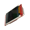
- Swap the OLED for a 1.8" ST7735 TFT for color and bigger digits
- Add an MPU6050 for tilt-aware orientation when a bike leans
- Pair with LoRa to broadcast live position to a chase vehicle
Expected result: You have a clear shortlist of next features once the basic GPS speedometer is working.
Conclusion
You built an Arduino Nano GPS speedometer using a NEO-6M GPS module and an SSD1306 OLED display to show live ground speed without any wheel sensor calibration. With a solid GPS lock outdoors, it is a simple and accurate way to get speed on a bike, motorcycle, or car.
Want the exact parts used in this build? Grab them from ShillehTek.com. If you want help customizing this project or building something for your product, check out our IoT consulting services.




.png?v=25000753014097803521791168436)

.png?v=68677308723310773341791168436)


