

Project Overview
ESP8266 + MH-Z19 WiFi CO2 monitor: In this project you build a compact IoT device that continuously measures indoor CO2 with an MH-Z19 NDIR sensor and reminds you to ventilate the room. A bicolor LED shows air quality at a glance, a piezo buzzer chirps when it is time to open a window, and anyone nearby can pull up live readings on their phone over WiFi with no app required.
- Time: About 2 hours
- Skill level: Beginner
- What you will build: A standalone WiFi CO2 monitor that serves live air-quality readings to any browser and alerts you with light and sound when CO2 gets too high.

Parts List
From ShillehTek
- MH-Z19C NDIR Infrared CO2 Sensor Module - the current-generation drop-in for the MH-Z19B used in the original build
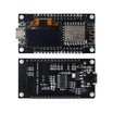
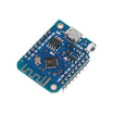
- NodeMCU ESP8266 Development Board (or the compact ESP8266 D1 Mini V3)
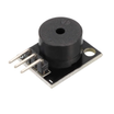
- KY-006 Passive Piezo Buzzer Module - any small piezo buzzer module works for the ventilation chirp
- 400-Point Solderless Breadboard
- 120pcs 20cm Dupont Jumper Wires
- Metal Film Resistor Kit - you need two about 68 ohm resistors for the LED
- Micro USB Cable for power and flashing
External
- Bicolor red/yellow 3mm LED (e.g. Kingbright L-115WEYW) - two separate red and yellow LEDs also work
Note: The original guide uses the MH-Z19B. The MH-Z19C is a newer revision of the same NDIR sensor family and wires up the same way for this project.
Step-by-Step Guide
Step 1 - Understand how the monitor works
Goal: Know what the device measures and how it decides when to warn you.
What to do: Nothing to wire yet. When people share a room, exhaled CO2 accumulates, and high CO2 correlates with a high aerosol load in the air.
The monitor samples the NDIR sensor and sorts the reading into three zones: green up to 1000 ppm, yellow from 1000 to 2000 ppm, and red above 2000 ppm.
Three alert thresholds drive the behavior: at roughly 1000 ppm the buzzer gives two short beeps and the LED turns yellow; above 2000 ppm you get three beeps and a red LED; and once ventilation brings the level back under about 800 ppm the device plays one long confirmation beep and the LED switches off so you know you can close the windows. To keep it from nagging, the audible alarm fires at most once per hour.
Expected result: You understand the three zones (green, yellow, red) and the beep patterns before building.
Step 2 - Wire the circuit
Goal: Connect the CO2 sensor, LED, and buzzer to the ESP8266.
What to do: Follow the breadboard schematic below. Power the sensor and buzzer from the 5V (VIN) and GND rails of the NodeMCU.
The CO2 sensor's signal line (orange in the diagram) and the buzzer's signal line (green) each go to a free GPIO pin, and the two LED legs connect through their own about 68 ohm resistors (pink for red, yellow for yellow) to two more GPIOs. Keep the wire colors consistent with the diagram and double-check the ground rail before powering up.

Expected result: A tidy breadboard with the sensor, buzzer, and LED all sharing power and ground with the ESP8266.
Step 3 - Prepare the Arduino IDE and flash the firmware
Goal: Get the project firmware onto your ESP8266.
What to do: Install the Arduino IDE and add ESP8266 board support through the Boards Manager.
Then grab the latest release of the original project's open-source firmware (the co2MeasurementDevice repository, linked from the credited write-up below), open the .ino sketch, select your NodeMCU board and port, and upload.
The project also ships web-interface files in a data folder. Upload those to the ESP8266 flash filesystem using the ESP8266 Sketch Data Upload tool so the built-in web pages work.
Expected result: The sketch compiles and flashes cleanly, and the filesystem upload finishes without errors.
Step 4 - Connect to the monitor's own WiFi
Goal: Read live CO2 values on your phone with zero network setup.
What to do: On first boot the device broadcasts its own access point named "CO2Measurement-XXXX". Join it from any phone or laptop, open a browser, and go to 10.10.10.1.
You land on the device's data page showing the current CO2 reading and air-quality zone.


Expected result: Everyone in the room can check the current CO2 level from their own seat.
Step 5 - Join your home WiFi (optional)
Goal: Put the monitor on your regular network so it lives alongside your other devices.
What to do: While connected in standalone mode, open the settings page and enter your home WiFi credentials. The device then joins your router and becomes reachable at the local IP address your router assigns it.


Expected result: The monitor appears on your LAN and any device in the house can open its data page.
Step 6 - Feed your smart home with XML data
Goal: Use the readings in home automation.
What to do: The firmware also exposes the current values as an XML file, so smart-home platforms can poll the device and trigger their own automations (fans, dashboards, and more).

Expected result: Your automation platform reads CO2 values straight from the device.
Step 7 - Know the quiet hours
Goal: Avoid surprises at night.
What to do: When connected to home WiFi, the firmware mutes the buzzer between 22:00 and 10:00 and switches WiFi off between 23:00 and 6:00 to save power. Power-cycling the ESP8266 wakes WiFi back up at night if you need it.
Expected result: No beeps while you sleep, and the monitor resumes normal operation in the morning.
Conclusion
You now have a self-contained air-quality station: an ESP8266 paired with an MH-Z19 NDIR CO2 sensor that color-codes your room's air, chirps when it is time to ventilate, and serves live readings to any browser on the network.
Photos and the original reference build are credited to Hackster.io (Felix and Tim Göhner).
Want the exact parts used in this build? Grab them from ShillehTek.com. If you want help customizing this project or building something for your product, check out our IoT consulting services.






.png?v=25000753014097803521791168436)

.png?v=68677308723310773341791168436)


