

Project Overview
Arduino Nano + MAX30102: Build a DIY pulse oximeter and heart rate monitor that reads the MAX30102 sensor over I2C and shows live BPM (and optional SpO2) on a 0.96 inch SSD1306 OLED.
This guide covers I2C wiring, installing the SparkFun MAX30102 library, basic smoothing and peak detection for cleaner BPM readings, and displaying results on an OLED.
- Time: 30 to 60 minutes
- Skill level: Beginner to Intermediate
- What you will build: A finger-based MAX30102 reader on Arduino with live OLED output for heart rate, plus notes for improving SpO2 accuracy.
Parts List
From ShillehTek
- Arduino Nano V3.0 - microcontroller used to read the sensor and drive the OLED.
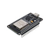
- ESP32 WROOM Dev Board - optional upgrade if you want WiFi logging later.
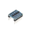
- I2C Logic Level Converter - use if you mix 3.3 V and 5 V I2C devices.
- 830-Point Breadboard - for quick prototyping.
- 351015 LiPo (3.7 V) - optional if you convert the build into a small wearable.
External
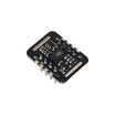
- MAX30102 breakout module (3.3 V) - heart rate and blood oxygen optical sensor.
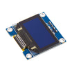
- 0.96 inch I2C OLED display (SSD1306, 128x64) - shows live readings.
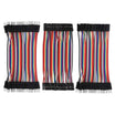
- Jumper wires - breadboard connections.
- USB cable - power and programming.
Note: The MAX30102 breakout is a 3.3 V device. Do not power it from 5 V. If your OLED or MCU uses 5 V logic on SDA/SCL, use a level shifter or confirm the module is 5 V tolerant on I2C.
Step-by-Step Guide
Step 1 - Understand what the MAX30102 measures
Goal: Know what the red and IR readings represent so the wiring and code behavior make sense.
What to do: The MAX30102 shines two LEDs into your finger: red (660 nm) and infrared (880 nm). A photodiode measures how much light returns after absorption by tissue and hemoglobin. The signal varies with each heartbeat as blood volume changes. The sensor samples this at high speed and sends raw values over I2C. Your code detects peaks (beats) for BPM and can compute a red/IR ratio for SpO2.

Expected result: You understand why the code looks for signal peaks (BPM) and why SpO2 requires more signal conditioning than simple BPM.
Step 2 - Wire the MAX30102 and OLED to the Arduino Nano (I2C)
Goal: Share the same I2C bus (SDA/SCL) between the MAX30102 and the SSD1306 OLED.
What to do: Use the wiring below. The MAX30102 must be powered from 3.3 V, not 5 V. The OLED is typically powered from 5 V on an Arduino Nano build, while sharing SDA/SCL on A4/A5.
Code:
MAX30102      Arduino Nano
VIN      ->   3.3V (NOT 5V - the sensor is 3.3V only)
GND      ->   GND
SDA      ->   A4
SCL      ->   A5
INT      ->   D2 (optional interrupt)

OLED I2C       Arduino Nano
VCC      ->   5V (many OLED modules tolerate I2C lines at either 5V or 3.3V)
GND      ->   GND
SDA      ->   A4 (shared bus)
SCL      ->   A5
Expected result: Both modules power on, and the I2C bus is shared on A4/A5 without loose connections.
Step 3 - Install the required Arduino libraries
Goal: Add the sensor and display libraries used by the example sketch.
What to do: In the Arduino IDE, go to Sketch → Include Library → Manage Libraries, then install:
-
SparkFun MAX3010x Pulse and Proximity Sensor Library(covers MAX30102 and MAX30105). -
Adafruit GFX LibraryandAdafruit SSD1306(for the OLED).
Expected result: The Arduino IDE can compile sketches that include MAX30105, heartRate, and Adafruit SSD1306 headers.
Step 4 - Upload a sketch that reads IR and displays BPM on the OLED
Goal: Verify the sensor is detected and see live IR and averaged BPM output.
What to do: Paste the sketch below into the Arduino IDE, select your board and COM port, then upload. Open the Serial Monitor at 115200 if you want to confirm initialization messages.
Code:
#include <MAX30105.h>
#include <heartRate.h>
#include <Wire.h>
#include <Adafruit_SSD1306.h>

MAX30105 particleSensor;
Adafruit_SSD1306 oled(128, 64, &Wire, -1);

const int RATE_SIZE = 4;
byte rates[RATE_SIZE];
byte rateSpot = 0;
long lastBeat = 0;
float beatsPerMinute = 0;
int beatAvg = 0;

void setup() {
  Serial.begin(115200);
  if (!particleSensor.begin(Wire, I2C_SPEED_FAST)) {
    Serial.println("MAX30102 not found");
    while (1);
  }
  particleSensor.setup();
  particleSensor.setPulseAmplitudeRed(0x0A);
  particleSensor.setPulseAmplitudeGreen(0);
  oled.begin(SSD1306_SWITCHCAPVCC, 0x3C);
}

void loop() {
  long irValue = particleSensor.getIR();
  if (checkForBeat(irValue)) {
    long delta = millis() - lastBeat;
    lastBeat = millis();
    beatsPerMinute = 60 / (delta / 1000.0);
    if (beatsPerMinute < 255 && beatsPerMinute > 20) {
      rates[rateSpot++] = (byte)beatsPerMinute;
      rateSpot %= RATE_SIZE;
      int sum = 0;
      for (byte i = 0; i < RATE_SIZE; i++) sum += rates[i];
      beatAvg = sum / RATE_SIZE;
    }
  }
  oled.clearDisplay();
  oled.setCursor(0, 0); oled.setTextSize(1); oled.setTextColor(WHITE);
  oled.print("IR: "); oled.println(irValue);
  oled.setTextSize(2);
  oled.print("BPM "); oled.println(beatAvg);
  oled.display();
}
Expected result: The OLED updates with the IR value and a BPM number that stabilizes after a few beats.
Step 5 - Improve measurement consistency (finger placement and lighting)
Goal: Reduce noise so the beat detector can lock onto a clean pulse waveform.
What to do: Use the tips below when taking a reading:

- Press your finger gently. Too much pressure can reduce blood flow.
- Keep your finger still for 10 seconds before trusting the value.
- Avoid bright ambient light hitting the sensor at an angle.
- For best SpO2 accuracy, run the SparkFun "SpO2" example sketch, which includes more complete signal conditioning.
Expected result: BPM readings fluctuate less and settle faster. SpO2 results improve when using the dedicated example.
Step 6 - (Optional) Plan the upgrade to a wearable
Goal: Understand the straightforward hardware changes needed to leave the breadboard.
What to do: If you want a wearable form factor, shrink the build to a smaller MCU board, add a TP4056 USB-C charger and a small LiPo battery, and mount everything in a 3D-printed finger clip. You can also add a button to start a 30-second reading and log to your phone over BLE.
Expected result: You have a clear path to turn the prototype into a compact, battery-powered device.
Step 7 - Read this caveat before using the readings
Goal: Use the project appropriately and safely.
What to do: Treat the MAX30102 as a learning, hobby, and fitness experimentation sensor. It is not a medical device. For real health decisions, use an FDA-cleared pulse oximeter.
Expected result: You understand the limits of the sensor and the build.
Conclusion
You built an Arduino Nano project that reads the MAX30102 over I2C and displays live heart rate data on an SSD1306 OLED, with guidance on improving stability and using the SparkFun SpO2 example for better oxygen estimation.
Want the exact parts used in this build? Grab them from ShillehTek.com. If you want help customizing this project or building something for your product, check out our IoT consulting services.
Attribution: This guide was inspired by "Guide to Using MAX30102 Heart Rate and Oxygen Sensor With Arduino" on Instructables. Images credited to the original author.





.png?v=25000753014097803521791168436)

.png?v=68677308723310773341791168436)


