Overview
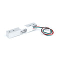
This is the sensor hiding under every bathroom scale: a 50 kg half-bridge strain gauge cell in a slim 34 x 34 x 7.8 mm package. Inside, two ~1 kΩ strain gauge resistors sit on a flexing metal plate — one stretched and one compressed as weight presses the center button — with three wires bringing out the bridge: white and black are the two ends, and red is the center tap between the gauges. Press on the cell and the red wire's voltage shifts by microvolts per gram, which an HX711 amplifier turns into clean digital weight readings.
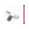
"Half-bridge" is the key word: one cell is half of the Wheatstone bridge that strain measurement needs. The classic build uses four of these cells, one under each corner of a platform — wired together, the four halves complete each other into a full bridge with 200 kg of combined capacity, exactly like a commercial body scale. Prefer a single cell? Two ordinary 1 kΩ resistors complete the bridge and give you a compact 0-50 kg sensor for one corner of whatever you are weighing.
Either way the readout side is identical to any load cell project: HX711 amplifier, a tare, a one-time calibration against a known weight, and gram-to-hectogram accuracy from Arduino, ESP32, Raspberry Pi, or Pico. Typical builds: DIY body scales, smart luggage checkers, keg and propane-tank level monitors, furniture occupancy sensing, and heavy-duty inventory shelves.
At a Glance
Specifications
| Parameter | Value |
| Sensor Type | Half-bridge resistive strain gauge |
| Rated Capacity | 50 kg per cell (4 cells = 200 kg platform) |
| Wiring | Red = signal (center tap), White & Black = bridge ends |
| Resistance | ~1 kΩ white-to-red and red-to-black (~2 kΩ end to end) |
| Sensitivity | ~1 mV/V at rated load (full-bridge configuration) |
| Recommended Excitation | ≤ 5V (supplied by the HX711) |
| Readout | HX711 24-bit amplifier (required — signal is microvolts) |
| Dimensions | 34 x 34 mm, 7.8 ± 0.2 mm thick, 14 mm center button |
| Body | Aluminum alloy plate with raised center contact |
| Overload Behavior | Brief overloads tolerated; sustained loads past rating skew calibration |
Pinout Diagram
Three wires, one rule: red is special. Measure with a multimeter and you will find about 1 kΩ from white to red and 1 kΩ from red to black — red is the tap between the two strain gauge halves (the "positive strain" and "negative strain" resistors), and its voltage is what shifts under load. The cell only flexes correctly when the center button carries the load and the outer rim sits on its mounting ring — which is why scale kits mount each cell in a plastic cradle that touches only the rim.

Wiring Guide
The wiring puzzle for these cells is on the bridge side, and it is the same for every microcontroller. Four-cell scale (200 kg): place one cell under each corner, then join the outer wires of neighboring cells in a ring — white to white on two opposite sides, black to black on the other two — so the four half-bridges chain into one full bridge. The four red wires then go to the HX711: one opposite pair to E+ and E-, the other opposite pair to A+ and A-. Single cell (50 kg): complete the bridge with two 1 kΩ resistors in series across E+ and E-; wire white to E+, black to E-, red to A+, and the resistor junction to A-. After that, the HX711-to-board wiring is the standard four pins.
Arduino Wiring
| Connection | Goes To | Details |
|---|---|---|
| 4 cells (corner ring) | HX711 E+, E-, A+, A- | Opposite reds to E pair, other reds to A pair |
| HX711 VCC | 5V | |
| HX711 GND | GND | |
| HX711 DT | D3 | |
| HX711 SCK | D2 |
ESP32 Wiring
| Connection | Goes To | Details |
|---|---|---|
| 4 cells (corner ring) | HX711 E+, E-, A+, A- | As described above |
| HX711 VCC | 3V3 | Keeps DT at 3.3V logic |
| HX711 GND | GND | |
| HX711 DT | GPIO 16 | |
| HX711 SCK | GPIO 4 |
Raspberry Pi Wiring
| Connection | Goes To | Details |
|---|---|---|
| 4 cells (corner ring) | HX711 E+, E-, A+, A- | As described above |
| HX711 VCC | Pin 1 (3.3V) | Never a 5V pin |
| HX711 GND | Pin 6 (GND) | |
| HX711 DT | Pin 29 (GPIO 5) | |
| HX711 SCK | Pin 31 (GPIO 6) |
Raspberry Pi Pico Wiring
| Connection | Goes To | Details |
|---|---|---|
| 4 cells (corner ring) | HX711 E+, E-, A+, A- | As described above |
| HX711 VCC | 3V3(OUT) (pin 36) | Do NOT use VBUS (5V) |
| HX711 GND | GND (pin 38) | |
| HX711 DT | GP14 (pin 19) | |
| HX711 SCK | GP15 (pin 20) |
Code Examples
Reading a 4-cell (or resistor-completed single-cell) bridge is identical to any HX711 project: tare empty, weigh a known object, divide to get your calibration factor. For a 200 kg scale, calibrate with something substantial — a person of known weight works far better than a 100 g weight at the bottom of the range.
Arduino
// 4x 50kg Load Cells + HX711 - Arduino Body Scale Example
// DT -> D3, SCK -> D2, VCC -> 5V
// Library: "HX711" by Bogdan Necula (bogde)

#include "HX711.h"

const int DT_PIN = 3;
const int SCK_PIN = 2;

// After calibrating: factor = tared raw reading / known weight in kg
float CALIBRATION_FACTOR = 1.0;

HX711 scale;

void setup() {
  Serial.begin(9600);
  scale.begin(DT_PIN, SCK_PIN);

  Serial.println("Empty the platform... taring in 3 s");
  delay(3000);
  scale.tare(20);
  scale.set_scale(CALIBRATION_FACTOR);
  Serial.println("Ready - step on!");
}

void loop() {
  if (scale.is_ready()) {
    float kg = scale.get_units(10);   // average of 10 samples
    long raw = scale.get_value(10);   // tared raw (for calibration)

    Serial.print("Raw: ");
    Serial.print(raw);
    Serial.print("  |  Weight: ");
    Serial.print(kg, 2);
    Serial.println(" kg");
  }
  delay(500);
}
ESP32 (Arduino IDE)
// 4x 50kg Load Cells + HX711 - ESP32 Example
// DT -> GPIO 16, SCK -> GPIO 4, VCC -> 3V3
// Library: "HX711" by Bogdan Necula

#include "HX711.h"

HX711 scale;
float CALIBRATION_FACTOR = 1.0;   // set after calibrating

void setup() {
  Serial.begin(115200);
  scale.begin(16, 4);               // DT, SCK

  Serial.println("Empty the platform... taring in 3 s");
  delay(3000);
  scale.tare(20);
  scale.set_scale(CALIBRATION_FACTOR);
  Serial.println("Ready - step on!");
}

void loop() {
  if (scale.wait_ready_timeout(1000)) {
    Serial.printf("Weight: %.2f kg\n", scale.get_units(10));
  }
  delay(500);
}
Raspberry Pi (Python)
#!/usr/bin/env python3
# 4x 50kg Load Cells + HX711 - Raspberry Pi Example (no library needed)
# DT -> GPIO 5 (pin 29), SCK -> GPIO 6 (pin 31), VCC -> 3.3V (pin 1)

import time
import RPi.GPIO as GPIO

DT, SCK = 5, 6
CALIBRATION_FACTOR = 1.0   # tared raw / known kg

GPIO.setmode(GPIO.BCM)
GPIO.setup(DT, GPIO.IN)
GPIO.setup(SCK, GPIO.OUT, initial=GPIO.LOW)

def read_raw():
    while GPIO.input(DT) == 1:      # wait for data ready
        time.sleep(0.001)
    value = 0
    for _ in range(24):             # 24 data bits
        GPIO.output(SCK, GPIO.HIGH)
        GPIO.output(SCK, GPIO.LOW)
        value = (value << 1) | GPIO.input(DT)
    GPIO.output(SCK, GPIO.HIGH)     # gain 128, channel A
    GPIO.output(SCK, GPIO.LOW)
    if value & 0x800000:
        value -= 1 << 24
    return value

def read_average(n=10):
    return sum(read_raw() for _ in range(n)) / n

print("Empty the platform... taring")
time.sleep(2)
zero = read_average(20)
print("Ready - step on!")

try:
    while True:
        kg = (read_average(10) - zero) / CALIBRATION_FACTOR
        print("Weight: {:.2f} kg".format(kg))
        time.sleep(0.5)
except KeyboardInterrupt:
    print("Stopped by user")
finally:
    GPIO.cleanup()
Raspberry Pi Pico (MicroPython)
# 4x 50kg Load Cells + HX711 - Pico MicroPython Example (no library)
# DT -> GP14, SCK -> GP15, VCC -> 3V3(OUT)

from machine import Pin
import time

dt = Pin(14, Pin.IN)
sck = Pin(15, Pin.OUT, value=0)

CALIBRATION_FACTOR = 1.0   # tared raw / known kg

def read_raw():
    while dt.value() == 1:
        time.sleep_ms(1)
    value = 0
    for _ in range(24):
        sck.value(1)
        sck.value(0)
        value = (value << 1) | dt.value()
    sck.value(1)               # gain 128, channel A
    sck.value(0)
    if value & 0x800000:
        value -= 1 << 24
    return value

def read_average(n=10):
    return sum(read_raw() for _ in range(n)) / n

print("Empty the platform... taring")
time.sleep(2)
zero = read_average(20)
print("Ready - step on!")

while True:
    kg = (read_average(10) - zero) / CALIBRATION_FACTOR
    print("Weight: {:.2f} kg".format(kg))
    time.sleep(0.5)