Overview
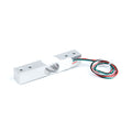
This kit is a complete digital scale front-end: a 5 kg aluminum bar load cell paired with the HX711, the 24-bit ADC that has become the standard way to read strain gauges with a microcontroller. The load cell converts weight into a tiny differential voltage (about 1 mV per volt of excitation at full load — a few millivolts total), and the HX711 amplifies that signal 128x and digitizes it into clean 24-bit readings your board fetches over a simple two-wire connection: DT (data) and SCK (clock).
Wiring is color-coded and hard to get wrong: the load cell's red, black, white, and green wires go to the HX711's E+, E-, A-, and A+ terminals, and the HX711's four output pins — GND, DT, SCK, VCC — go to your microcontroller. The bar cell mounts as a cantilever: bolt one end to a base, bolt your weighing platform to the other end (watch the arrow on the cell — it points in the direction of the applied load), and every gram on the platform flexes the aluminum beam by a calibrated whisper.
After a quick one-time calibration with any object of known weight, expect steady gram-level readings across the 0-5 kg range — the recipe behind kitchen scales, filament monitors, parts counters, beehive trackers, pet-food dispensers, and lab experiments on Arduino, ESP32, Raspberry Pi, and Pico.
At a Glance
Specifications
| Parameter | Value |
| Amplifier / ADC | HX711 24-bit sigma-delta with programmable gain |
| Channels | A (gain 128 or 64, used by the load cell) + B (gain 32, spare) |
| Supply Voltage | 2.6 - 5.5V (logic level follows VCC) |
| Output Rate | 10 SPS default (80 SPS via the chip's RATE pin on some boards) |
| Interface | 2-wire serial: DT (data out) + SCK (clock in) — not I2C/SPI |
| Load Cell Type | Full-bridge strain gauge, aluminum single-point bar |
| Rated Capacity | 5 kg |
| Sensitivity | 1.0 ± 0.15 mV/V |
| Combined Error | ≤ 0.05% of full scale |
| Load Cell Wires | Red E+, Black E-, White A-, Green A+ |
| Bar Dimensions | ~75 x 12.7 x 12.7 mm, threaded mounting holes both ends |
| Achievable Resolution | Gram-level across 0-5 kg after calibration |
Pinout Diagram
Two connections to make. Load cell to HX711: red to E+, black to E-, white to A-, green to A+ (E is the excitation the HX711 supplies to the bridge; A is the amplified sense channel). HX711 to your board: VCC and GND for power, DT and SCK to any two GPIO pins — the HX711 speaks its own simple clocked protocol, so no special I2C/SPI pins are required. The B-/B+ pads are a spare second channel you can ignore.

Wiring Guide
Arduino Wiring
Power the HX711 from 5V; DT and SCK go to two ordinary digital pins.
| HX711 Pin | Arduino Pin |
|---|---|
| VCC | 5V |
| GND | GND |
| DT | D3 |
| SCK | D2 |
ESP32 Wiring
Power the HX711 from 3V3 — the chip runs happily there, and its DT output then swings at 3.3V, exactly what ESP32 inputs want.
| HX711 Pin | ESP32 Pin | Details |
|---|---|---|
| VCC | 3V3 | Keeps DT at 3.3V logic |
| GND | GND | |
| DT | GPIO 16 | |
| SCK | GPIO 4 |
Raspberry Pi Wiring
Same 3.3V rule as the ESP32. DT and SCK land on two free GPIOs.
| HX711 Pin | Raspberry Pi Pin | Details |
|---|---|---|
| VCC | Pin 1 (3.3V) | Never a 5V pin |
| GND | Pin 6 (GND) | |
| DT | Pin 29 (GPIO 5) | |
| SCK | Pin 31 (GPIO 6) |
Raspberry Pi Pico Wiring
| HX711 Pin | Pico Pin | Details |
|---|---|---|
| VCC | 3V3(OUT) (pin 36) | Do NOT use VBUS (5V) |
| GND | GND (pin 38) | |
| DT | GP14 (pin 19) | |
| SCK | GP15 (pin 20) |
Code Examples
Calibration is a one-time, two-step ritual every scale needs: tare with nothing on the platform, place a known weight, and compute scale_factor = raw_change / known_weight. Each example below prints raw values first so you can find your own factor, then converts to grams.
Arduino
Install the "HX711" library by Bogdan Necula (bogde) from the Library Manager.
// 5kg Load Cell + HX711 - Arduino Example
// DT -> D3, SCK -> D2, VCC -> 5V, GND -> GND
// Library: "HX711" by Bogdan Necula (bogde)

#include "HX711.h"

const int DT_PIN = 3;
const int SCK_PIN = 2;

// Start with 1.0, then calibrate:
// factor = (raw with weight - raw empty) / weight in grams
float CALIBRATION_FACTOR = 1.0;

HX711 scale;

void setup() {
  Serial.begin(9600);
  scale.begin(DT_PIN, SCK_PIN);

  Serial.println("Remove all weight... taring in 3 s");
  delay(3000);
  scale.tare();                       // zero the empty platform
  scale.set_scale(CALIBRATION_FACTOR);
  Serial.println("Ready. Place a known weight to calibrate,");
  Serial.println("or start weighing if already calibrated.");
}

void loop() {
  if (scale.is_ready()) {
    // Average 10 readings for a steady value
    float grams = scale.get_units(10);
    long raw = scale.get_value(10);   // tared raw counts (for calibration)

    Serial.print("Raw: ");
    Serial.print(raw);
    Serial.print("  |  Weight: ");
    Serial.print(grams, 1);
    Serial.println(" g");
  } else {
    Serial.println("HX711 not responding - check wiring");
  }
  delay(500);
}
ESP32 (Arduino IDE)
// 5kg Load Cell + HX711 - ESP32 Example
// DT -> GPIO 16, SCK -> GPIO 4, VCC -> 3V3, GND -> GND
// Library: "HX711" by Bogdan Necula (works on ESP32)

#include "HX711.h"

const int DT_PIN = 16;
const int SCK_PIN = 4;

float CALIBRATION_FACTOR = 1.0;  // set after calibrating

HX711 scale;

void setup() {
  Serial.begin(115200);
  scale.begin(DT_PIN, SCK_PIN);

  Serial.println("Remove all weight... taring in 3 s");
  delay(3000);
  scale.tare();
  scale.set_scale(CALIBRATION_FACTOR);
  Serial.println("Ready.");
}

void loop() {
  if (scale.wait_ready_timeout(1000)) {
    float grams = scale.get_units(10);
    Serial.printf("Weight: %.1f g\n", grams);
  } else {
    Serial.println("HX711 not responding - check wiring");
  }
  delay(500);
}
Raspberry Pi (Python)
Dependency-free: this reads the HX711 protocol directly with RPi.GPIO.
#!/usr/bin/env python3
# 5kg Load Cell + HX711 - Raspberry Pi Example (no library needed)
# DT -> GPIO 5 (pin 29), SCK -> GPIO 6 (pin 31), VCC -> 3.3V (pin 1)

import time
import RPi.GPIO as GPIO

DT, SCK = 5, 6
CALIBRATION_FACTOR = 1.0   # (raw_with_weight - raw_empty) / grams

GPIO.setmode(GPIO.BCM)
GPIO.setup(DT, GPIO.IN)
GPIO.setup(SCK, GPIO.OUT, initial=GPIO.LOW)

def read_raw():
    # Wait until the HX711 signals data ready (DT goes low)
    while GPIO.input(DT) == 1:
        time.sleep(0.001)

    value = 0
    for _ in range(24):                 # clock out 24 data bits
        GPIO.output(SCK, GPIO.HIGH)
        GPIO.output(SCK, GPIO.LOW)
        value = (value << 1) | GPIO.input(DT)

    GPIO.output(SCK, GPIO.HIGH)         # 25th pulse = channel A, gain 128
    GPIO.output(SCK, GPIO.LOW)

    if value & 0x800000:                # sign-extend the 24-bit result
        value -= 1 << 24
    return value

def read_average(n=10):
    return sum(read_raw() for _ in range(n)) / n

print("Remove all weight... taring")
time.sleep(2)
zero = read_average(20)
print("Tared. Raw zero = {:.0f}".format(zero))

try:
    while True:
        raw = read_average(10)
        grams = (raw - zero) / CALIBRATION_FACTOR
        print("Raw: {:8.0f}  |  Weight: {:8.1f} g".format(raw - zero, grams))
        time.sleep(0.5)
except KeyboardInterrupt:
    print("Stopped by user")
finally:
    GPIO.cleanup()
Raspberry Pi Pico (MicroPython)
# 5kg Load Cell + HX711 - Pico MicroPython Example (no library needed)
# DT -> GP14, SCK -> GP15, VCC -> 3V3(OUT), GND -> GND

from machine import Pin
import time

dt = Pin(14, Pin.IN)
sck = Pin(15, Pin.OUT, value=0)

CALIBRATION_FACTOR = 1.0   # (raw_with_weight - raw_empty) / grams

def read_raw():
    while dt.value() == 1:          # wait for data ready
        time.sleep_ms(1)

    value = 0
    for _ in range(24):             # clock out 24 data bits
        sck.value(1)
        sck.value(0)
        value = (value << 1) | dt.value()

    sck.value(1)                    # 25th pulse = channel A, gain 128
    sck.value(0)

    if value & 0x800000:            # sign-extend
        value -= 1 << 24
    return value

def read_average(n=10):
    return sum(read_raw() for _ in range(n)) / n

print("Remove all weight... taring")
time.sleep(2)
zero = read_average(20)
print("Tared. Raw zero =", int(zero))

while True:
    raw = read_average(10)
    grams = (raw - zero) / CALIBRATION_FACTOR
    print("Raw: {:8.0f}  |  Weight: {:8.1f} g".format(raw - zero, grams))
    time.sleep(0.5)