Overview
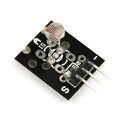
The KY-026 is an infrared flame sensor module that detects fire by sensing the infrared light open flames emit in the 760-1100 nm wavelength band. An IR-sensitive photodiode picks up the flame's radiation and an onboard LM393 comparator converts that signal into two usable outputs: an analog output (A0) that tracks IR intensity continuously, and a digital output (D0) that switches HIGH the moment intensity crosses a threshold you set with the blue trimmer potentiometer. Operating anywhere from 3.3V to 5V, it works with Arduino, ESP32, Raspberry Pi, and Raspberry Pi Pico.
The two outputs make the module flexible. Use D0 when you just need a yes/no answer — a candle flame appears in the sensor's roughly 60-degree field of view and the pin goes HIGH, the onboard status LED lights, and your code reacts. Use A0 when you want to measure how strong the IR source is, for example to estimate whether a flame is growing or shrinking. Detection distance depends on flame size: a small lighter flame is typically detectable from around 60-100 cm, while larger flames register from farther away.
Makers use the KY-026 for pilot-light and flame-out monitoring, fire-fighting robot competitions, candle-triggered projects, and IoT fire alert experiments. One important note before you start: this is a hobby-grade sensor module, not a certified fire safety device. It is perfect for learning and prototyping, but never rely on it as your only protection against fire — use proper smoke and fire alarms for real safety.
At a Glance
Specifications
| Parameter | Value |
| Operating Voltage | 3.3V - 5V DC |
| Maximum Current | ~15 mA |
| Detected Wavelength | 760 - 1100 nm (infrared) |
| Detection Angle | ~60 degrees |
| Detection Range | ~60 - 100 cm for a lighter flame (larger flames detect farther) |
| Comparator Chip | LM393 dual differential comparator |
| Sensor Element | 5 mm IR-sensitive photodiode |
| Analog Output (A0) | Continuous voltage tracking IR intensity |
| Digital Output (D0) | HIGH when IR exceeds the potentiometer-set threshold |
| Sensitivity Adjustment | Blue trimmer potentiometer (threshold for D0) |
| Indicator LEDs | 2 (power + D0 status) |
| Board Dimensions | ~36 x 15 mm |
Pinout Diagram
The KY-026 has four male header pins. A0 is the analog output — a continuous voltage that changes with the infrared intensity reaching the photodiode. G is ground, and + is the supply pin (3.3V or 5V, matched to your board). D0 is the digital output from the LM393 comparator: it sits LOW normally and switches HIGH when flame IR crosses the threshold set by the blue trimmer potentiometer. The board also carries a power LED and a second LED that mirrors the D0 state, which makes threshold tuning easy to see.

Wiring Guide
Arduino Wiring
The Arduino Uno is the simplest platform for the KY-026. It runs 5V logic and has built-in analog inputs, so you can power the module from 5V and connect both outputs directly — no level shifting or external ADC needed.
| KY-026 Pin | Arduino Pin |
|---|---|
| A0 | A0 |
| G | GND |
| + | 5V |
| D0 | Digital Pin 2 |
ESP32 Wiring
The ESP32 uses 3.3V GPIO, so power the KY-026 from the 3V3 pin. The module works fine at 3.3V, and — critically — its A0 and D0 outputs can never swing higher than the supply, which keeps them safe for ESP32 inputs.
| KY-026 Pin | ESP32 Pin | Details |
|---|---|---|
| A0 | GPIO 34 | ADC1 channel, input-only pin |
| G | GND | |
| + | 3V3 | Do NOT use VIN/5V |
| D0 | GPIO 25 |
Raspberry Pi Wiring
The Raspberry Pi has no built-in analog-to-digital converter, so on the Pi you use the digital output D0. Power the module from the Pi's 3.3V rail so D0 idles and switches at 3.3V levels — perfectly safe for Pi GPIO.
| KY-026 Pin | Raspberry Pi Pin | Details |
|---|---|---|
| A0 | Not connected | Pi has no ADC — see note below |
| G | Pin 6 (GND) | |
| + | Pin 1 (3.3V) | Do NOT use a 5V pin |
| D0 | Pin 11 (GPIO 17) |
Raspberry Pi Pico Wiring
The Pico is a great match for the KY-026 because it combines 3.3V GPIO with a built-in ADC, so you get both the digital trigger and the analog intensity reading. Power the module from the 3V3(OUT) pin.
| KY-026 Pin | Pico Pin | Details |
|---|---|---|
| A0 | GP26 (physical pin 31) | ADC0 input |
| G | GND (physical pin 38) | |
| + | 3V3(OUT) (physical pin 36) | Do NOT use VBUS (5V) |
| D0 | GP15 (physical pin 20) |
Code Examples
Each example reads the digital output for reliable flame detection and (where the board has an ADC) prints the raw analog value so you can watch IR intensity in real time. Analog behavior varies between KY-026 board revisions — on many boards the reading drops as flame intensity rises, while some revisions rise instead — so run the code, note your no-flame baseline, and briefly introduce a lighter flame at a safe distance to see which way your board moves.
Arduino
// KY-026 Flame Sensor - Arduino Example
// A0 -> A0, D0 -> Digital Pin 2, + -> 5V, G -> GND

const int analogPin = A0;   // analog IR intensity
const int digitalPin = 2;   // comparator flame output

void setup() {
  Serial.begin(9600);
  pinMode(digitalPin, INPUT);
}

void loop() {
  // Read raw IR intensity (0-1023)
  int analogValue = analogRead(analogPin);

  // Read the comparator output: HIGH = flame above threshold
  int flameState = digitalRead(digitalPin);

  Serial.print("Analog: ");
  Serial.print(analogValue);

  if (flameState == HIGH) {
    Serial.println("  |  FLAME DETECTED!");
  } else {
    Serial.println("  |  No flame");
  }

  // Watch the analog value with and without a flame to learn
  // your board's baseline, then adjust the potentiometer so
  // D0 triggers exactly when you want it to.
  delay(500);
}
ESP32 (MicroPython)
# KY-026 Flame Sensor - ESP32 MicroPython Example
# A0 -> GPIO 34, D0 -> GPIO 25, + -> 3V3, G -> GND

from machine import ADC, Pin
import time

# GPIO 34 is an ADC1 channel, so it keeps working with Wi-Fi on
analog = ADC(Pin(34))
analog.atten(ADC.ATTN_11DB)   # full 0 - 3.3V input range

digital = Pin(25, Pin.IN)     # comparator flame output

while True:
    raw = analog.read()               # 0 - 4095
    voltage = raw * 3.3 / 4095

    if digital.value() == 1:
        state = "FLAME DETECTED!"
    else:
        state = "No flame"

    print("Analog: {} ({:.2f} V)  |  {}".format(raw, voltage, state))
    time.sleep(0.5)
Raspberry Pi (Python)
#!/usr/bin/env python3
# KY-026 Flame Sensor - Raspberry Pi Example
# D0 -> GPIO 17 (physical pin 11), + -> 3.3V (pin 1), G -> GND (pin 6)
# The Pi has no ADC, so we use the digital output only.

import RPi.GPIO as GPIO
import time

DO_PIN = 17

GPIO.setmode(GPIO.BCM)
GPIO.setup(DO_PIN, GPIO.IN)

try:
    print("Monitoring KY-026 flame sensor (Ctrl+C to stop)...")
    last_state = GPIO.input(DO_PIN)

    while True:
        state = GPIO.input(DO_PIN)

        # Only print when the state changes
        if state != last_state:
            if state == GPIO.HIGH:
                print("FLAME DETECTED!")
            else:
                print("Flame no longer detected.")
            last_state = state

        time.sleep(0.1)

except KeyboardInterrupt:
    print("Stopped by user")
finally:
    GPIO.cleanup()
Raspberry Pi Pico (MicroPython)
# KY-026 Flame Sensor - Pico MicroPython Example
# A0 -> GP26 (ADC0), D0 -> GP15, + -> 3V3(OUT), G -> GND

from machine import ADC, Pin
import time

analog = ADC(26)            # GP26 = ADC0
digital = Pin(15, Pin.IN)   # comparator flame output

while True:
    raw = analog.read_u16()          # 0 - 65535
    voltage = raw * 3.3 / 65535

    if digital.value() == 1:
        state = "FLAME DETECTED!"
    else:
        state = "No flame"

    print("Analog: {} ({:.2f} V)  |  {}".format(raw, voltage, state))
    time.sleep(0.5)