Overview
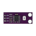
The APDS-9960 is a four-in-one optical sensor that packs gesture recognition, proximity detection, RGB color sensing, and ambient light measurement into a single tiny chip — the same sensor family that powered the screen-off swipe gestures on the Samsung Galaxy S5. This module puts the APDS-9960 on a compact purple GY-9960 breakout board with six pins (VL, GND, VCC, SDA, SCL, INT), letting you add touchless swipe controls, hand detection, and color measurement to Arduino, ESP32, Raspberry Pi, and Raspberry Pi Pico projects over a simple I2C connection at address 0x39.
Inside the sensor, a 950 nm infrared LED illuminates whatever passes above the module, and four directional photodiodes feed an on-chip gesture engine that classifies the motion as up, down, left, or right — no math required on your microcontroller. The same IR system measures proximity out to roughly 10-20 cm depending on target reflectivity and LED drive settings, while a separate set of UV/IR-filtered photodiodes delivers 16-bit red, green, blue, and clear light readings. An open-drain, active-low INT pin can wake your code only when something interesting happens, and I2C runs at up to 400 kHz.
The one thing to know before wiring anything: the APDS-9960 is a 3.3V-only part. Its supply range is 2.4-3.6V and its I2C pins are not 5V tolerant, so it connects directly to the ESP32, Raspberry Pi, and Pico, but a 5V Arduino Uno needs the module powered from 3.3V with a logic level converter on the data lines. Mature libraries — SparkFun's APDS-9960 library for Arduino and Adafruit's CircuitPython driver for Raspberry Pi — mean you can go from unboxing to reading gestures in a few minutes.
At a Glance
Specifications
| Parameter | Value |
| Sensing Functions | Gesture, proximity, RGB color, ambient light |
| Operating Voltage (VCC) | 2.4V - 3.6V DC (3.3V typical) |
| Logic Level | 3.3V only - NOT 5V tolerant |
| Interface | I2C, up to 400 kHz (Fast Mode) |
| I2C Address | 0x39 (fixed, 7-bit) |
| Gesture Directions | Up, down, left, right (plus near/far events) |
| Proximity / Gesture Range | Up to ~10-20 cm (depends on reflectivity and LED drive) |
| Color / Light Resolution | 16-bit per channel (red, green, blue, clear) with UV/IR blocking filters |
| IR LED Wavelength | 950 nm (integrated, factory calibrated) |
| Operating Current | ~790 uA gesture/proximity, 250 uA light sensing, 38 uA wait, 1-10 uA sleep |
| Interrupt Output | INT pin, open drain, active low |
| Operating Temperature | -30°C to +85°C |
Pinout Diagram
The module breaks out six pins. VCC (2.4-3.6V) and GND power the sensor, SDA and SCL carry the I2C bus, and INT is the open-drain, active-low interrupt output that pulls low when a gesture, proximity, or light threshold event fires. VL is an optional separate supply (3.0-4.5V) for the onboard infrared LED — you only connect it if you open the PS solder jumper on the back of the board; with PS closed (the factory default), the IR LED runs from VCC and VL can be left unconnected.

Two solder jumpers on the back of the breakout configure the board. PS ties the IR LED supply to VCC so the whole module runs from one 3.3V rail (leave it closed unless you have a reason to power the LED separately through VL). I2C PU connects the onboard pull-up resistors on SDA and SCL to VCC — it ships closed on most boards, which means you normally do not need external pull-up resistors.
Wiring Guide
Arduino Wiring
The Arduino Uno runs 5V logic, but the APDS-9960 is a 3.3V-only sensor. Power the module from the Uno's 3.3V pin and pass SDA, SCL, and INT through a bi-directional logic level converter (5V high side, 3.3V low side).
| Module Pin | Arduino Pin | Details |
|---|---|---|
| VL | Not connected | PS jumper closed (default) |
| GND | GND | Shared with level converter GND |
| VCC | 3.3V | Never 5V - also feeds converter LV side |
| SDA | A4 (SDA) | Via logic level converter |
| SCL | A5 (SCL) | Via logic level converter |
| INT | D2 | Via logic level converter |
ESP32 Wiring
The ESP32 is a 3.3V board, so the APDS-9960 connects directly with no level shifting. The table uses the ESP32's default I2C pins, GPIO 21 (SDA) and GPIO 22 (SCL).
| Module Pin | ESP32 Pin | Details |
|---|---|---|
| VL | Not connected | PS jumper closed (default) |
| GND | GND | |
| VCC | 3V3 | Never VIN/5V |
| SDA | GPIO 21 | Default I2C SDA |
| SCL | GPIO 22 | Default I2C SCL |
| INT | GPIO 19 | Optional, for interrupt-driven code |
Raspberry Pi Wiring
The Raspberry Pi's GPIO header is 3.3V, so the APDS-9960 wires directly to the standard I2C1 pins. Enable I2C first with sudo raspi-config (Interface Options, then I2C).
| Module Pin | Raspberry Pi Pin | Details |
|---|---|---|
| VL | Not connected | PS jumper closed (default) |
| GND | Pin 6 (GND) | |
| VCC | Pin 1 (3.3V) | Never pin 2/4 (5V) |
| SDA | Pin 3 (GPIO 2, SDA1) | |
| SCL | Pin 5 (GPIO 3, SCL1) | |
| INT | Pin 11 (GPIO 17) | Optional, for interrupt-driven code |
Raspberry Pi Pico Wiring
The Pico is a 3.3V board, so the sensor connects directly. This table uses the I2C0 peripheral on GP0/GP1, which matches the MicroPython example below.
| Module Pin | Pico Pin | Details |
|---|---|---|
| VL | Not connected | PS jumper closed (default) |
| GND | Pin 38 (GND) | |
| VCC | Pin 36 (3V3 OUT) | Never VBUS/VSYS |
| SDA | GP0 (pin 1) | I2C0 SDA |
| SCL | GP1 (pin 2) | I2C0 SCL |
| INT | GP2 (pin 4) | Optional, for interrupt-driven code |
Code Examples
Arduino
Install the "SparkFun APDS9960 RGB and Gesture Sensor" library from the Arduino IDE Library Manager. This sketch uses the INT line on D2 so the sensor only interrupts your code when a gesture is in progress.
// APDS-9960 Gesture Sensor - Arduino Uno Example
// SDA: A4, SCL: A5, INT: D2 (all through a logic level converter)
// VCC: 3.3V (NOT 5V)
// Library: "SparkFun APDS9960 RGB and Gesture Sensor" (Library Manager)

#include <Wire.h>
#include <SparkFun_APDS9960.h>

#define APDS9960_INT 2  // INT pin, active low

SparkFun_APDS9960 apds = SparkFun_APDS9960();
volatile bool isr_flag = false;

void interruptRoutine() {
  isr_flag = true;  // Keep the ISR short - just set a flag
}

void setup() {
  Serial.begin(9600);
  pinMode(APDS9960_INT, INPUT);
  attachInterrupt(digitalPinToInterrupt(APDS9960_INT), interruptRoutine, FALLING);

  // Initialize I2C and the sensor's default settings
  if (apds.init()) {
    Serial.println(F("APDS-9960 initialized"));
  } else {
    Serial.println(F("Init failed! Check wiring and 3.3V power."));
  }

  // Start the gesture engine with interrupts enabled
  if (apds.enableGestureSensor(true)) {
    Serial.println(F("Gesture sensor running - swipe over the sensor!"));
  } else {
    Serial.println(F("Could not start the gesture engine."));
  }
}

void loop() {
  if (isr_flag) {
    detachInterrupt(digitalPinToInterrupt(APDS9960_INT));
    handleGesture();
    isr_flag = false;
    attachInterrupt(digitalPinToInterrupt(APDS9960_INT), interruptRoutine, FALLING);
  }
}

void handleGesture() {
  if (apds.isGestureAvailable()) {
    switch (apds.readGesture()) {
      case DIR_UP:    Serial.println("UP");    break;
      case DIR_DOWN:  Serial.println("DOWN");  break;
      case DIR_LEFT:  Serial.println("LEFT");  break;
      case DIR_RIGHT: Serial.println("RIGHT"); break;
      case DIR_NEAR:  Serial.println("NEAR");  break;
      case DIR_FAR:   Serial.println("FAR");   break;
      default:        Serial.println("NONE");
    }
  }
}
ESP32 (Arduino IDE)
The same SparkFun library works on the ESP32 with no changes — install "SparkFun APDS9960 RGB and Gesture Sensor" from the Library Manager and select your ESP32 board. This example polls proximity plus RGB color and ambient light, so only SDA and SCL are required.
// APDS-9960 Proximity + RGB Color - ESP32 Arduino Example
// SDA: GPIO 21, SCL: GPIO 22 (ESP32 default I2C pins), VCC: 3V3
// Library: "SparkFun APDS9960 RGB and Gesture Sensor" (Library Manager)

#include <Wire.h>
#include <SparkFun_APDS9960.h>

SparkFun_APDS9960 apds = SparkFun_APDS9960();

uint8_t proximity = 0;
uint16_t ambient = 0, red = 0, green = 0, blue = 0;

void setup() {
  Serial.begin(9600);
  Wire.begin(21, 22);  // SDA = GPIO 21, SCL = GPIO 22

  if (apds.init()) {
    Serial.println("APDS-9960 initialized");
  } else {
    Serial.println("Init failed! Check wiring and 3V3 power.");
  }

  // Start the proximity engine (false = no interrupts, we poll instead)
  if (!apds.enableProximitySensor(false)) {
    Serial.println("Could not start proximity sensor");
  }

  // Start the ambient light / RGB color engine
  if (!apds.enableLightSensor(false)) {
    Serial.println("Could not start light sensor");
  }

  delay(500);  // Give the sensor time to settle
}

void loop() {
  apds.readProximity(proximity);      // 0 (nothing near) to 255 (very close)
  apds.readAmbientLight(ambient);     // 16-bit clear channel
  apds.readRedLight(red);
  apds.readGreenLight(green);
  apds.readBlueLight(blue);

  Serial.print("Proximity: ");
  Serial.print(proximity);
  Serial.print(" | Ambient: ");
  Serial.print(ambient);
  Serial.print(" | R: ");
  Serial.print(red);
  Serial.print(" G: ");
  Serial.print(green);
  Serial.print(" B: ");
  Serial.println(blue);

  delay(500);
}
Raspberry Pi (Python)
This example uses Adafruit's CircuitPython driver through Blinka. Enable I2C in raspi-config, then install the library with pip3 install adafruit-circuitpython-apds9960 (on newer Raspberry Pi OS releases, install it inside a virtual environment).
#!/usr/bin/env python3
# APDS-9960 Gesture Sensor - Raspberry Pi Example
# SDA: Pin 3 (GPIO 2), SCL: Pin 5 (GPIO 3), VCC: Pin 1 (3.3V)
#
# Setup:
#   sudo raspi-config          (Interface Options - enable I2C)
#   pip3 install adafruit-circuitpython-apds9960

import time
import board
import busio
from adafruit_apds9960.apds9960 import APDS9960

# Create the I2C bus and the sensor object (address 0x39)
i2c = busio.I2C(board.SCL, board.SDA)
sensor = APDS9960(i2c)

# The gesture engine needs the proximity engine running as well
sensor.enable_proximity = True
sensor.enable_gesture = True

# gesture() returns 0 = none, 1 = up, 2 = down, 3 = left, 4 = right
names = {1: "UP", 2: "DOWN", 3: "LEFT", 4: "RIGHT"}

print("Swipe a hand 5-15 cm over the sensor (Ctrl+C to stop)...")

try:
    while True:
        gesture = sensor.gesture()
        if gesture:
            print("Gesture:", names.get(gesture, "UNKNOWN"))
        time.sleep(0.05)
except KeyboardInterrupt:
    print("Stopped by user")
Raspberry Pi Pico (MicroPython)
There is no official vendor MicroPython driver for the APDS-9960, so this example is deliberately dependency-free: it talks to the sensor's registers directly over I2C to read proximity — nothing to install beyond MicroPython itself. If you want full gesture decoding on the Pico, flash CircuitPython instead and use the same verified adafruit-circuitpython-apds9960 library shown in the Raspberry Pi example (copied to the board as a .mpy bundle).
# APDS-9960 Proximity Reading - Raspberry Pi Pico MicroPython Example
# SDA: GP0, SCL: GP1 (I2C0), VCC: 3V3 OUT (pin 36)
# No external library needed - reads the sensor registers directly.

from machine import Pin, I2C
import time

APDS_ADDR  = 0x39   # Fixed I2C address of the APDS-9960
REG_ENABLE = 0x80   # Power / feature enable register
REG_PPULSE = 0x8E   # Proximity IR pulse configuration
REG_ID     = 0x92   # Device ID register
REG_PDATA  = 0x9C   # Proximity data register

i2c = I2C(0, sda=Pin(0), scl=Pin(1), freq=400000)

# Sanity check: the sensor should answer at 0x39
if APDS_ADDR not in i2c.scan():
    raise RuntimeError("APDS-9960 not found at 0x39 - check wiring")

chip_id = i2c.readfrom_mem(APDS_ADDR, REG_ID, 1)[0]
print("Device ID: 0x{:02X}".format(chip_id))

# 8 IR pulses of 16 us each (same default the SparkFun library uses)
i2c.writeto_mem(APDS_ADDR, REG_PPULSE, b'\x87')

# ENABLE register: PON (bit 0) powers the chip, PEN (bit 2)
# starts the proximity engine -> 0b00000101 = 0x05
i2c.writeto_mem(APDS_ADDR, REG_ENABLE, b'\x05')
time.sleep_ms(10)

while True:
    # PDATA: 0 (nothing in range) up to 255 (object right at the lens)
    prox = i2c.readfrom_mem(APDS_ADDR, REG_PDATA, 1)[0]
    print("Proximity:", prox)
    time.sleep_ms(200)