Overview
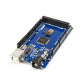
The Leonardo R3 is an Arduino-compatible development board built on the ATmega32U4 — a microcontroller with USB support built directly into the chip. Unlike the UNO or Mega, which use a separate USB-to-serial converter, the Leonardo talks to your computer natively. That single difference unlocks its party trick: it can appear to your PC as a keyboard, mouse, or MIDI device, making it the classic board for macro pads, game controllers, automation buttons, and assistive input devices.
Beyond HID emulation, it is a normal Arduino: 20 digital I/O pins (7 PWM), 12 analog inputs, and full Arduino IDE support with the familiar shield footprint. Programming, power, and serial monitoring all happen over one USB cable — there is nothing to wire to get started.
At a Glance
Specifications
| Parameter | Value |
| Microcontroller | ATmega32U4 (8-bit AVR, native USB) |
| Clock Speed | 16 MHz |
| Operating Voltage | 5V |
| Input Voltage (VIN / barrel jack) | 7-12V recommended |
| Digital I/O Pins | 20 (7 provide PWM) |
| Analog Input Pins | 12 (10-bit ADC) |
| Flash Memory | 32 KB (4 KB used by bootloader) |
| SRAM / EEPROM | 2.5 KB / 1 KB |
| USB Interface | Built into ATmega32U4 (CDC serial + HID) |
| Hardware UART | Serial1 on pins 0 (RX) and 1 (TX) |
| DC Current per I/O Pin | 20 mA recommended (40 mA absolute max) |
| Dimensions | 68.6 x 53.3 mm |
Getting Started
The Leonardo is a USB-powered host board — nothing needs wiring before your first upload. Connect it with a USB cable and set up the IDE as below.
1. Configure the Arduino IDE
| IDE Setting | Value |
|---|---|
| Board | Arduino Leonardo |
| Port | The port labeled "Arduino Leonardo" |
2. Understand the upload behavior
Because USB runs on the same chip as your sketch, the Leonardo briefly disconnects and re-enumerates as a different port during every upload. This is normal — the IDE handles it automatically. If an upload ever fails repeatedly, press and release the reset button just as the IDE reports "Uploading..." to catch the bootloader window manually.
3. Powering the board
USB supplies 5V for normal use. For standalone projects, feed 7-12V into the barrel jack or VIN pin. The 3.3V pin can supply up to 50 mA for low-voltage sensors.
Code Examples
Blink + Serial (first upload test)
// Leonardo R3 - Blink the onboard LED (pin 13) and print to Serial

const int LED_PIN = 13;

void setup() {
  pinMode(LED_PIN, OUTPUT);
  Serial.begin(9600);
  while (!Serial) { ; }        // wait for USB serial (Leonardo-specific)
  Serial.println("Leonardo R3 is alive!");
}

void loop() {
  digitalWrite(LED_PIN, HIGH);
  delay(500);
  digitalWrite(LED_PIN, LOW);
  delay(500);
}
USB keyboard emulation (one-key macro)
// Leonardo R3 - Type a text macro when a button is pressed.
// Wiring: pushbutton between pin 2 and GND (uses internal pull-up).
// The button guard keeps the keyboard idle until YOU trigger it.

#include <Keyboard.h>

const int BUTTON_PIN = 2;
bool lastState = HIGH;

void setup() {
  pinMode(BUTTON_PIN, INPUT_PULLUP);
  Keyboard.begin();
}

void loop() {
  bool state = digitalRead(BUTTON_PIN);

  // Falling edge = button just pressed
  if (state == LOW && lastState == HIGH) {
    Keyboard.print("Hello from ShillehTek!");
    delay(50);                 // simple debounce
  }
  lastState = state;
}