ZMPT101B AC Single-Phase Voltage Sensor Module for Arduino, Raspberry Pi & ESP32Default Title · $6.99 · In stock
Overview
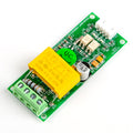
The ZMPT101B AC Voltage Sensor lets your microcontroller measure mains AC voltage safely. At its heart is a ZMPT101B precision voltage transformer with a 2 mA : 2 mA ratio: the high-voltage side connects to the AC source through a screw terminal, and the low-voltage side drives an on-board LM358 op-amp stage that scales the waveform down to something an ADC can read. Because the coupling is a transformer, the measurement side is galvanically isolated from the mains side.
The module outputs an analog sine wave centered at half the supply voltage, so both halves of the AC cycle fit inside the ADC range. A multi-turn trimmer potentiometer sets the gain, letting you match the output swing to your ADC and your expected input voltage (up to 250 V RMS). Reading the true RMS voltage is then a software job: sample fast for a few complete cycles, subtract the DC bias, and take the root mean square.
This manual covers the pinout, wiring for Arduino, ESP32, Raspberry Pi, and Raspberry Pi Pico, RMS-sampling code for each platform, and how to calibrate the module against a multimeter. Combined with a current sensor or an energy meter like the PZEM-004T, it forms the voltage half of a complete AC power monitor.
At a Glance
Sensor Type
ZMPT101B 2 mA : 2 mA transformer
Measures
AC voltage up to 250 V RMS
Output
Analog, biased at VCC/2
Supply Voltage
3.3 – 5.5 V DC
Isolation
Galvanic (transformer-coupled)
Interface
Single analog pin
Specifications
Parameter
Value
Voltage transformer
ZMPT101B, 2 mA : 2 mA current-type
Measurable voltage
Up to 250 V AC RMS
Mains frequency
50 / 60 Hz
Supply voltage
3.3 – 5.5 V DC (5 V typical)
Output signal
Analog sine wave centered at VCC/2
On-board amplifier
LM358 dual op-amp
Gain adjustment
Multi-turn trimmer potentiometer
Isolation
Transformer-isolated AC input
AC input
2-position screw terminal (L / N)
Header pins
4-pin: 5V · OUT · GND · GND
Typical accuracy
±1 % after calibration
Board size
Approx. 50 × 20 mm
Pinout Diagram
The AC source under test lands on the two-position screw terminal (L and N — polarity does not matter for a voltage reading). The 4-pin header on the other side carries the low-voltage interface: 5V (VCC), OUT (the analog signal), and two GND pins that are internally connected. The trimmer potentiometer between them sets the amplifier gain.
Wiring Guide
Arduino Uno Wiring
ZMPT101B Pin
Arduino Uno Pin
Notes
5V
5V
Output idles at ~2.5 V (VCC/2)
OUT
A0
Analog waveform in
GND
GND
Either GND pin
AC terminal (L / N)
AC source under test
Screw terminal — isolated from the header side
Mains voltage can kill. The screw terminal side of this board carries live mains. De-energize the circuit before touching the wiring, use insulated ferrules, keep the board in an enclosure, and never probe the AC side while it is powered. If you are not comfortable working with mains, test with a low-voltage AC source (e.g. a 12 V AC adapter) first.
ESP32 Wiring
ZMPT101B Pin
ESP32 Pin
Notes
5V
3V3
Powering at 3.3 V centers the output at ~1.65 V, inside the ADC range
OUT
GPIO 34
ADC1 input-only pin
GND
GND
Either GND pin
AC terminal (L / N)
AC source under test
Isolated screw terminal
Stay on ADC1. GPIO 32–36 and 39 belong to ADC1, which keeps working while Wi-Fi is on. ADC2 pins stop converting as soon as Wi-Fi starts. If the waveform clips, back the trimpot off until the sine wave fits the 0–3.3 V window.
Raspberry Pi Wiring (via ADS1115 ADC)
Connection
Raspberry Pi / ADS1115
Notes
ZMPT101B 5V
3.3V (Pin 1)
Keeps OUT within the ADS1115 input range
ZMPT101B OUT
ADS1115 A0
Analog waveform
ZMPT101B GND
GND (Pin 6)
Common ground
ADS1115 VDD / GND
3.3V (Pin 1) / GND
Power the ADC from 3.3 V
ADS1115 SDA / SCL
GPIO 2 (Pin 3) / GPIO 3 (Pin 5)
I2C — enable with sudo raspi-config
Why the extra chip? The Raspberry Pi has no analog inputs. An ADS1115 running at its maximum 860 samples/s captures enough points per 50/60 Hz cycle for a usable RMS calculation.
Raspberry Pi Pico Wiring
ZMPT101B Pin
Pico Pin
Notes
5V
3V3(OUT) (Pin 36)
Output idles at ~1.65 V
OUT
GP26 / ADC0 (Pin 31)
12-bit ADC (read as 16-bit in MicroPython)
GND
GND (Pin 38)
Either GND pin
AC terminal (L / N)
AC source under test
Isolated screw terminal
Sample whole cycles. A 200 ms window covers exactly 10 cycles at 50 Hz and 12 at 60 Hz, so the RMS math is not skewed by a partial cycle at the end of the window.
Code Examples
Arduino — True-RMS Voltage Reading
zmpt101b_rms.ino
const int SENSOR_PIN = A0;
float CAL = 250.0;   // scale factor - tune against a multimeter

void setup() {
  Serial.begin(9600);
}

void loop() {
  const unsigned long windowMs = 200;  // 10 cycles @ 50 Hz, 12 @ 60 Hz
  unsigned long start = millis();
  unsigned long n = 0;
  double sum = 0, sumSq = 0;

  while (millis() - start < windowMs) {
    int raw = analogRead(SENSOR_PIN);
    sum += raw;
    sumSq += (double)raw * raw;
    n++;
  }

  double mean = sum / n;                       // DC bias (~512)
  double variance = sumSq / n - mean * mean;
  double rmsCounts = sqrt(variance > 0 ? variance : 0);
  double volts = rmsCounts * (5.0 / 1023.0) * CAL;

  Serial.print("AC voltage: ");
  Serial.print(volts, 1);
  Serial.println(" V");
  delay(500);
}
ESP32 — RMS Reading on ADC1
esp32_zmpt101b.ino
const int SENSOR_PIN = 34;   // ADC1 input-only pin
float CAL = 250.0;           // tune against a multimeter

void setup() {
  Serial.begin(115200);
  analogSetPinAttenuation(SENSOR_PIN, ADC_11db);  // full 0-3.3 V range
}

void loop() {
  const unsigned long windowMs = 200;
  unsigned long start = millis();
  unsigned long n = 0;
  double sum = 0, sumSq = 0;

  while (millis() - start < windowMs) {
    int raw = analogRead(SENSOR_PIN);   // 0-4095
    sum += raw;
    sumSq += (double)raw * raw;
    n++;
  }

  double mean = sum / n;
  double variance = sumSq / n - mean * mean;
  double rmsCounts = sqrt(variance > 0 ? variance : 0);
  double volts = rmsCounts * (3.3 / 4095.0) * CAL;

  Serial.printf("AC voltage: %.1f V\n", volts);
  delay(500);
}
Raspberry Pi — Python with ADS1115
zmpt101b_ads1115.py
import time
import math
import board
import busio
import adafruit_ads1x15.ads1115 as ADS
from adafruit_ads1x15.analog_in import AnalogIn

# pip3 install adafruit-circuitpython-ads1x15

i2c = busio.I2C(board.SCL, board.SDA)
ads = ADS.ADS1115(i2c)
ads.data_rate = 860          # fastest rate - needed for 50/60 Hz
chan = AnalogIn(ads, ADS.P0)

CAL = 250.0                  # tune against a multimeter

def read_rms(window_s=0.2):
    samples = []
    end = time.monotonic() + window_s
    while time.monotonic() < end:
        samples.append(chan.voltage)
    mean = sum(samples) / len(samples)
    var = sum((v - mean) ** 2 for v in samples) / len(samples)
    return math.sqrt(var) * CAL

while True:
    print("AC voltage: {:.1f} V".format(read_rms()))
    time.sleep(1)
Raspberry Pi Pico — MicroPython
pico_zmpt101b.py
from machine import ADC
import math
import time

adc = ADC(26)                # GP26 / ADC0
CAL = 250.0                  # tune against a multimeter

def read_rms(window_ms=200):
    n = 0
    total = 0
    total_sq = 0
    t_end = time.ticks_add(time.ticks_ms(), window_ms)
    while time.ticks_diff(t_end, time.ticks_ms()) > 0:
        raw = adc.read_u16()
        total += raw
        total_sq += raw * raw
        n += 1
    mean = total / n
    var = total_sq / n - mean * mean
    rms = math.sqrt(var if var > 0 else 0)
    return rms * (3.3 / 65535) * CAL

while True:
    print("AC voltage: {:.1f} V".format(read_rms()))
    time.sleep(1)
Frequently Asked Questions
Why does OUT read about half the supply voltage with nothing connected?
That is by design. The op-amp stage biases the output at VCC/2 so the negative half of the AC sine wave can be represented by an ADC that only reads positive voltages. With no AC input you see a flat line at the bias point — roughly 512 counts on a 10-bit Arduino ADC at 5 V.
How do I calibrate the module?
Two knobs: hardware gain and the software scale factor. First set the trimpot so the waveform uses most of the ADC range at your highest expected voltage without clipping. Then measure the actual mains voltage with a trusted multimeter and adjust the CAL constant until the sketch prints the same value. Calibration holds well as long as you do not move the trimpot afterwards.
Can it measure DC voltage?
No. The ZMPT101B is a transformer, and transformers only couple alternating current. A DC input produces no output at all. For DC measurements use a resistor divider or a dedicated DC voltage sensor instead.
Is it safe to connect this to mains?
The transformer galvanically isolates the microcontroller side from the AC side, which is a real safety advantage over a bare resistor divider. But the screw terminal, its solder pads, and your AC wiring are still live mains. Work de-energized, insulate every exposed conductor, mount the board in an enclosure, and treat the AC side with the same respect you would give any mains circuit.
Can I run it from 3.3 V?
Yes. The LM358 stage works at 3.3 V and the output then centers at ~1.65 V, which suits the ESP32 and Pico ADCs directly. Headroom is smaller, so you may need to lower the gain slightly, and you should recalibrate CAL after changing the supply voltage.
My readings jump around. How do I stabilize them?
Sample in windows that cover whole cycles (200 ms works for both 50 and 60 Hz), keep the sampling loop tight with no serial printing inside it, and average two or three consecutive RMS results. Also check the trimpot: a waveform that clips at the ADC rails produces erratic, compressed readings.
Does it measure current or power too?
No — voltage only. Pair it with a current transformer (such as an SCT-013) to compute real power yourself, or use an integrated meter like the PZEM-004T, which reports voltage, current, power, and energy over one serial link.
Reference documents for the ZMPT101B AC Single-Phase Voltage Sensor Module for Arduino, Raspberry Pi & ESP32. This manual covers wiring and code; the documents below carry the full electrical specifications.