

Project Overview
ESP8266 + ZMPT101B true-RMS voltmeter: Build a calibrated AC voltage meter using an ESP8266 (D1 Mini/NodeMCU) and the ZMPT101B voltage sensor module, then publish live readings to an Adafruit IO MQTT dashboard or a local Android app.
- Time: 2 to 3 hours (including calibration)
- Skill level: Intermediate (mains electricity involved - read the safety note)
- What you will build: A calibrated true-RMS voltmeter on an ESP8266 with WiFi reporting via MQTT and an optional local phone app.

Safety first: This project connects to live AC mains. Insulate every high-voltage connection, never touch the circuit while energized, and if you are not comfortable working around powerline voltage, do not proceed.
Parts List
From ShillehTek
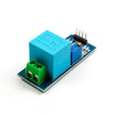
- ZMPT101B AC Single-Phase Voltage Sensor Module - isolated voltage sensing with an analog output for the ADC.
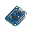
- ESP8266 D1 Mini V3 Pre-Soldered - WiFi microcontroller to sample A0 and publish readings (any ESP8266 works; the original used a NodeMCU 12E).
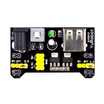
- MB102 Breadboard Power Supply (3.3V/5V) - provides stable sensor power to reduce reading drift.
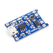
- TP4056 LiPo Charging Board - optional for a battery-powered variant.
- 830-Point Breadboard - prototyping the low-voltage wiring.
- Dupont Jumper Wires - making reliable breadboard connections.
External
- A test load: an incandescent bulb behind a triac-based light dimmer is ideal
- A true-RMS multimeter (for one-time slope calibration)
- Android phone (optional, for the local app)
Note: The ZMPT101B module offsets the waveform around your board mid-rail (2.5 V on 5 V boards, about 1.65 V on 3.3 V boards like the ESP8266) so the signal shape stays intact for true-RMS math.
Step-by-Step Guide
Step 1 - Why true RMS matters
Goal: Understand the measurement problem that cheap meters and naive code get wrong.
What to do: A clean 50/60 Hz sine wave is easy: measure the peak and divide by √2. But with a triac dimmer in the circuit, the waveform is chopped and the first part of every half-cycle can be missing. Averaging-type meters (and simple peak-based sketches) can read badly wrong. True RMS computed from sampled data works on any waveform shape.

Expected result: You know why this build outperforms a non-true-RMS measurement approach.
Step 2 - Understand the ZMPT101B module
Goal: Know what the sensor module is doing electrically.
What to do: The ZMPT101B module uses a small voltage transformer (galvanic isolation from mains) plus an op-amp stage that scales and offsets the stepped-down waveform so it fits your ADC input range while preserving waveform shape.


Expected result: You understand the signal path from mains terminals to the ESP8266 ADC pin.
Step 3 - Provide stable power to the sensor
Goal: Reduce reading drift caused by supply sag on some ESP8266 setups.
What to do: Some ESP8266 boards can show supply sag over USB that makes readings wobble. Power the ZMPT101B module from a stable 3.3 V source, such as a battery through a converter, or an MB102 breadboard supply.

Expected result: A stable sensor supply that improves measurement stability.
Step 4 - Wire the ZMPT101B to the ESP8266 and connect the test bench
Goal: Connect the module safely and prepare a controllable AC waveform source.
What to do: Low-voltage side: VCC to 3.3V, GND to GND, OUT to A0 on the ESP8266. Mains side: the module screw terminals go across the voltage you are measuring. The example setup uses a bulb fed through a triac dimmer so you can change the waveform on demand. Maximum input is 250 VAC.

Expected result: Hardware is wired correctly and the high-voltage side is insulated.
Step 5 - Calibrate gain using the onboard potentiometer
Goal: Set amplification so the waveform fills the ADC range without clipping.
What to do: Apply your maximum expected voltage (for example, about 230 V from the socket). Run a raw analogRead sketch and use the Serial Plotter while turning the ZMPT101B potentiometer until the waveform is large but not clipped.


Expected result: Maximum usable amplitude with zero clipping.
Step 6 - Upload true-RMS code and calibrate the zero offset (intercept)
Goal: Compute true RMS from samples and remove the residual offset.
What to do: Install the Filters library. The key parameters are windowLength (100/testFrequency works well on the ESP8266), intercept, and slope.
Code:
#include <Filters.h>

float testFrequency = 50;                    // your mains frequency (Hz)
float windowLength = 100.0 / testFrequency;  // sample window; 40/f on 5V Arduinos
int sensorPin = A0;

double intercept = 0;   // set after the zero-volt test
double slope = 1;       // set after the multimeter comparison
double currentVolts;

unsigned long printPeriod = 1000;
unsigned long previousMillis = 0;

RunningStatistics inputStats;

void setup() {
  Serial.begin(115200);
  inputStats.setWindowSecs(windowLength);
}

void loop() {
  inputStats.input(analogRead(sensorPin));   // sample continuously

  if (millis() - previousMillis >= printPeriod) {
    previousMillis = millis();
    currentVolts = intercept + slope * inputStats.sigma();
    Serial.print("Voltage: ");
    Serial.println(currentVolts, 1);
  }
}
Next, feed the module 0 VAC and observe the reading. Whatever nonzero value remains becomes your negative intercept.


Expected result: A zeroed reading at 0 VAC, ready for scaling.
Step 7 - Calibrate slope against a true-RMS multimeter
Goal: Convert the RMS statistic into real volts.
What to do: Apply mains voltage again and compare the ESP8266 reading to your trusted meter. Example: if the board reports 90.5 and the multimeter says 228.6 V, set slope = 228.6 / 90.5. Enter the slope and re-upload.

Expected result: A calibrated true-RMS AC voltmeter.
Step 8 - Publish readings to Adafruit IO over MQTT
Goal: Display voltage on a cloud dashboard with history and alerts.
What to do: In Adafruit IO, create a feed, then a dashboard with a gauge block bound to that feed. Copy your AIO key. In the Arduino IDE, install the Adafruit MQTT library. Add your WiFi credentials, username, key, and feed name to the sketch and upload.


Expected result: Live voltage visible in Adafruit IO with optional alerts and history.
Step 9 - Optional: use the local Android app instead of the cloud
Goal: View voltage on your phone without using a cloud service.
What to do: Use the alternative sketch that runs a small web server on the ESP8266 and returns the latest reading to clients. The companion Android app (built in MIT App Inventor 2) connects to the ESP8266 IP address and fetches the value on demand.


Expected result: Phone-readable line voltage on your local network, with a base you can extend further.
Conclusion
You built and calibrated a ZMPT101B-based true-RMS AC voltmeter on an ESP8266 that stays accurate even when a triac dimmer mangles the waveform. You also added WiFi reporting either to an Adafruit IO MQTT dashboard or to a local Android app.
Want the exact parts used in this build? Grab them from ShillehTek.com. If you want help customizing this project or building something for your product, check out our IoT consulting services.
Credits: Photos and reference project are credited to SurtrTech on Hackster.io.




.png?v=25000753014097803521791168436)

.png?v=68677308723310773341791168436)


