Overview
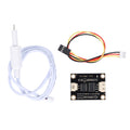
The PZEM-004T is the module that turns "I wonder what that appliance costs to run" into hard numbers. Clamp its split-core current transformer around a live wire, give the board a voltage reference from the same circuit, and it measures everything that matters on a single-phase AC line: voltage, current, active power, energy (kWh), frequency, and power factor — all computed on-board to metering-grade accuracy and served over a simple TTL UART using Modbus-RTU at 9600 baud.
The design keeps your microcontroller a safe distance from the mains: the measurement side and the communication side are galvanically separated by optocouplers, and the current sensing itself is a clip-on CT that never touches copper. Your Arduino, ESP32, Pi, or Pico only ever sees four low-voltage wires — 5V, GND, TX, RX — while the module does its work across the isolation barrier. The 100A CT version covers everything from a phone charger to a whole subpanel.
Classic builds: whole-house energy dashboards, per-appliance cost logging, solar/generator monitoring, detecting when the washing machine finishes (power drops), and Home Assistant integrations. One rule stands above all of them: the screw-terminal side carries lethal mains voltage. Wire it de-energized, insulate it in an enclosure, and treat that end of the board with the respect you'd give any breaker panel.
At a Glance
Specifications
| Parameter | Value |
| Model | PZEM-004T V3.0, 100A variant with split-core CT |
| Voltage Measurement | 80 - 260V AC, resolution 0.1V (±0.5%) |
| Current Measurement | 0 - 100A via CT, starting current 0.02A (±0.5%) |
| Power | 0 - 23 kW active power, resolution 0.1W |
| Energy | 0 - 9999.99 kWh, stored through power loss, resettable by command |
| Frequency / PF | 45 - 65 Hz (±0.5%) / power factor 0.00 - 1.00 |
| Interface | TTL UART 9600 8N1, Modbus-RTU protocol, default address 0xF8 |
| Isolation | Optocoupler-isolated UART between mains side and logic side |
| Interface Power | 5V on the 4-pin connector (~10 mA) |
| Terminals | L, N (voltage sense) + 2x CT secondary |
| Alarm | Programmable over-power alarm threshold |
Pinout Diagram
Mains side (screw terminal): L and N sense the line voltage; the other two screws take the CT's secondary wires. The CT itself clamps around the LIVE conductor only — never around both wires of a cord, or the fields cancel and current reads zero. Logic side (4-pin connector): 5V, RX, TX, GND to your microcontroller, crossed as usual (module TX to your RX).

Wiring Guide
Arduino Wiring (Uno: SoftwareSerial / Mega: Serial3)
| PZEM Pin | Arduino Pin | Details |
|---|---|---|
| 5V | 5V | Interface power |
| GND | GND | |
| TX | D10 (Uno) / RX3 (Mega) | Module transmits |
| RX | D11 (Uno) / TX3 (Mega) | Module receives |
| L / N / CT | Mains + CT clamp | CT around LIVE wire only |
ESP32 Wiring (hardware UART2)
| PZEM Pin | ESP32 Pin | Details |
|---|---|---|
| 5V | VIN (5V) | Interface wants 5V |
| GND | GND | |
| TX | GPIO 16 (RX2) | Opto output is 3.3V-safe in practice |
| RX | GPIO 17 (TX2) | 3.3V drive works through the opto |
Raspberry Pi Wiring (UART or USB-TTL)
| PZEM Pin | Pi Pin | Details |
|---|---|---|
| 5V | Pin 2 (5V) | |
| GND | Pin 6 (GND) | |
| TX | Pin 10 (GPIO 15, RXD) | |
| RX | Pin 8 (GPIO 14, TXD) |
Raspberry Pi Pico Wiring (UART0)
| PZEM Pin | Pico Pin | Details |
|---|---|---|
| 5V | VBUS (pin 40) | USB 5V |
| GND | GND (pin 38) | |
| TX | GP1 (UART0 RX) | |
| RX | GP0 (UART0 TX) |
Code Examples
The Arduino-family examples use the PZEM004Tv30 library (Library Manager). The Pi and Pico examples speak Modbus-RTU directly — no library needed beyond pyserial on the Pi.
Arduino
// PZEM-004T V3 - Arduino Example
// TX->D10, RX->D11 (Uno, SoftwareSerial) | Library: "PZEM004Tv30"

#include <PZEM004Tv30.h>
#include <SoftwareSerial.h>

SoftwareSerial pzemSerial(10, 11);   // RX, TX
PZEM004Tv30 pzem(pzemSerial);

void setup() {
  Serial.begin(115200);
  Serial.println("PZEM-004T energy monitor");
}

void loop() {
  float voltage = pzem.voltage();
  float current = pzem.current();
  float power   = pzem.power();
  float energy  = pzem.energy();
  float freq    = pzem.frequency();
  float pf      = pzem.pf();

  if (isnan(voltage)) {
    Serial.println("No response - check wiring and mains presence");
  } else {
    Serial.print(voltage);  Serial.print(" V | ");
    Serial.print(current);  Serial.print(" A | ");
    Serial.print(power);    Serial.print(" W | ");
    Serial.print(energy, 3);Serial.print(" kWh | ");
    Serial.print(freq);     Serial.print(" Hz | PF ");
    Serial.println(pf);
  }
  delay(1000);
}
ESP32 (Arduino IDE)
// PZEM-004T V3 - ESP32 Example (hardware UART2)
// TX->GPIO16, RX->GPIO17 | Library: "PZEM004Tv30"

#include <PZEM004Tv30.h>

PZEM004Tv30 pzem(Serial2, 16, 17);   // UART2, RX=16, TX=17

void setup() {
  Serial.begin(115200);
}

void loop() {
  float v = pzem.voltage();
  if (isnan(v)) {
    Serial.println("No response from PZEM");
  } else {
    Serial.printf("%.1f V  %.3f A  %.1f W  %.3f kWh  %.1f Hz  PF %.2f\n",
                  v, pzem.current(), pzem.power(),
                  pzem.energy(), pzem.frequency(), pzem.pf());
  }
  delay(1000);

  // pzem.resetEnergy();   // uncomment once to zero the kWh counter
}
Raspberry Pi (Python, Modbus-RTU)
#!/usr/bin/env python3
# PZEM-004T V3 - Raspberry Pi Example (raw Modbus-RTU)
# TX->GPIO15, RX->GPIO14 (or use /dev/ttyUSB0)
# Install: pip3 install pyserial

import serial, struct, time

def crc16(data):
    crc = 0xFFFF
    for byte in data:
        crc ^= byte
        for _ in range(8):
            if crc & 1:
                crc = (crc >> 1) ^ 0xA001
            else:
                crc >>= 1
    return crc

port = serial.Serial("/dev/serial0", 9600, timeout=1)

# Read 10 input registers from address 0xF8
request = bytes([0xF8, 0x04, 0x00, 0x00, 0x00, 0x0A])
request += struct.pack("<H", crc16(request))

while True:
    port.write(request)
    resp = port.read(25)
    if len(resp) == 25:
        regs = struct.unpack(">10H", resp[3:23])
        voltage = regs[0] / 10
        current = (regs[1] + (regs[2] << 16)) / 1000
        power   = (regs[3] + (regs[4] << 16)) / 10
        energy  = (regs[5] + (regs[6] << 16)) / 1000
        freq    = regs[7] / 10
        pf      = regs[8] / 100
        print(f"{voltage:.1f} V  {current:.3f} A  {power:.1f} W  "
              f"{energy:.3f} kWh  {freq:.1f} Hz  PF {pf:.2f}")
    else:
        print("No/short response - check wiring and mains")
    time.sleep(1)
Raspberry Pi Pico (MicroPython)
# PZEM-004T V3 - Pico MicroPython Example (raw Modbus-RTU)
# TX->GP1, RX->GP0, 5V->VBUS

from machine import UART, Pin
import struct, time

uart = UART(0, baudrate=9600, tx=Pin(0), rx=Pin(1), timeout=300)

def crc16(data):
    crc = 0xFFFF
    for byte in data:
        crc ^= byte
        for _ in range(8):
            crc = (crc >> 1) ^ 0xA001 if crc & 1 else crc >> 1
    return crc

req = bytes([0xF8, 0x04, 0x00, 0x00, 0x00, 0x0A])
req += struct.pack("<H", crc16(req))

while True:
    uart.write(req)
    time.sleep_ms(200)
    resp = uart.read()
    if resp and len(resp) >= 25:
        regs = struct.unpack(">10H", resp[3:23])
        voltage = regs[0] / 10
        current = (regs[1] + (regs[2] << 16)) / 1000
        power   = (regs[3] + (regs[4] << 16)) / 10
        energy  = (regs[5] + (regs[6] << 16)) / 1000
        print("{:.1f} V  {:.3f} A  {:.1f} W  {:.3f} kWh".format(
            voltage, current, power, energy))
    else:
        print("No response - check wiring and mains")
    time.sleep(1)