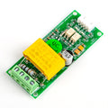
MQ-7 Carbon Monoxide (CO) Gas Sensor Module for Arduino, Raspberry Pi & ESP32Default Title · $6.99 · In stock
Overview
The MQ-7 Gas Sensor Module detects carbon monoxide (CO) in the 20–2000 ppm range. Inside the stainless mesh can sits a tin-dioxide (SnO₂) sensing element on a heater: when CO molecules reach the heated surface, the element’s resistance drops, and the module converts that change into an analog voltage on the A0 pin. Higher CO concentration means a higher A0 voltage.
Like all Flying-Fish-style MQ modules, it also gives you a digital output: an on-board LM393 comparator drives D0 low when the analog level crosses a threshold you set with the trimmer potentiometer, so you can trigger an alarm with no ADC at all. Two LEDs show power and threshold status. The heater draws around 150 mA from 5 V, so give the module a solid supply rather than a breadboard rail shared with everything else.
Two expectations to set before you start: a fresh sensor needs a 24–48 hour burn-in before its readings settle, and this module is a hobby sensor for experiments and relative measurements — it is not a certified life-safety CO alarm. This manual covers the pinout, wiring for Arduino, ESP32, Raspberry Pi, and Pico (including the voltage divider that 3.3 V boards need), reading code for each, and the practical limits of what an MQ-7 can tell you.
At a Glance
Detects
Carbon monoxide (CO)
Range
20 – 2000 ppm
Outputs
A0 analog + D0 comparator
Supply
5 V, heater ~150 mA
Burn-In
24 – 48 h for stable readings
Important
Not a certified safety device
Specifications
Parameter
Value
Sensing element
MQ-7, tin dioxide (SnO₂) on heater
Target gas
Carbon monoxide (CO)
Detection range
20 – 2000 ppm
Supply voltage
5 V DC
Heater consumption
~150 mA (≈350 mW)
Analog output (A0)
0 V up to near VCC, rises with CO
Digital output (D0)
LM393 comparator, active LOW, trimpot threshold
Indicators
Power LED + threshold LED
Burn-in time
24 – 48 h (first use)
Warm-up per session
Several minutes minimum
Datasheet heater cycle
60 s @ 5 V / 90 s @ 1.4 V (module runs fixed 5 V)
Header
4-pin: A0 · D0 · GND · VCC
Pinout Diagram
Four pins on the right edge of the board: A0 (analog CO signal), D0 (digital threshold output, active low), GND, and VCC (5 V). The trimmer potentiometer sets the D0 threshold — clockwise is typically more sensitive on these boards.
Wiring Guide
Arduino Uno Wiring
MQ-7 Pin
Arduino Uno Pin
Notes
VCC
5V
Heater draws ~150 mA
GND
GND
Common ground
A0
A0
5 V board reads it directly
D0
D2 (optional)
Goes LOW when the trimpot threshold is crossed
Not a life-safety device. This module is for experiments, data logging, and relative comparisons. It must never be the thing standing between people and CO poisoning — use a certified CO alarm for that. CO is odorless and lethal; treat any real-world test gas with extreme care and ventilation.
ESP32 Wiring
MQ-7 Pin
ESP32 Pin
Notes
VCC
VIN (5V)
Heater needs 5 V — 3.3 V starves it
GND
GND
Common ground
A0
10k/20k divider → GPIO 34
A0 can reach ~5 V; the divider scales it to ≤3.3 V
D0
Not recommended directly
Also swings to 5 V — divide it too if you need it
The divider. A0 → 10 kΩ → GPIO 34, with 20 kΩ from GPIO 34 to GND. Output is 2/3 of the sensor voltage (5 V becomes 3.33 V), and the code multiplies by 1.5 to recover the real value. GPIO 34 is on ADC1, which keeps working with Wi-Fi active.
Raspberry Pi Wiring (via ADS1115 ADC)
Connection
Raspberry Pi / ADS1115
Notes
MQ-7 VCC
5V (Pin 2)
Heater supply
MQ-7 GND
GND (Pin 6)
Common ground
MQ-7 A0
10k/20k divider → ADS1115 A0
Keeps the input under the ADC’s 3.3 V supply
ADS1115 VDD / GND
3.3V (Pin 1) / GND
Power the ADC from 3.3 V
ADS1115 SDA / SCL
GPIO 2 (Pin 3) / GPIO 3 (Pin 5)
I2C — enable in raspi-config
Why the ADS1115? The Pi has no analog inputs, and the MQ-7’s signal is a slowly moving DC level — exactly what a 16-bit I2C ADC reads well. One ADS1115 gives you four channels, so a whole MQ-series sensor array fits on one chip.
Raspberry Pi Pico Wiring
MQ-7 Pin
Pico Pin
Notes
VCC
VBUS (Pin 40)
5 V from USB for the heater
GND
GND (Pin 38)
Common ground
A0
10k/20k divider → GP26 / ADC0 (Pin 31)
Scales the 0–5 V signal into the 3.3 V ADC range
D0
Unused
5 V logic — divide it if you need the comparator output
Let it warm up. Readings drift downward for the first several minutes of every session while the heater reaches temperature. Log the value only after it levels off, and expect the baseline to keep improving over the first day or two of a brand-new sensor’s life.
Code Examples
Arduino — Analog + Threshold Readout
mq7_reader.ino
const int AO_PIN = A0;
const int DO_PIN = 2;

void setup() {
  Serial.begin(9600);
  pinMode(DO_PIN, INPUT);
  Serial.println("MQ-7 warming up (give it several minutes)...");
}

void loop() {
  int raw = analogRead(AO_PIN);
  float voltage = raw * (5.0 / 1023.0);
  bool alarm = digitalRead(DO_PIN) == LOW;  // LOW = threshold crossed

  Serial.print("Raw: ");
  Serial.print(raw);
  Serial.print("  Voltage: ");
  Serial.print(voltage, 2);
  Serial.print(" V  Threshold: ");
  Serial.println(alarm ? "EXCEEDED" : "ok");
  delay(1000);
}
ESP32 — Reading Through the Divider
esp32_mq7.ino
// MQ-7 A0 -> 10k/20k divider -> GPIO 34 (see wiring tab)
const int AO_PIN = 34;
const float DIVIDER = 1.5;   // recovers the pre-divider voltage

void setup() {
  Serial.begin(115200);
  analogSetPinAttenuation(AO_PIN, ADC_11db);  // full 0-3.3 V range
}

void loop() {
  int raw = analogRead(AO_PIN);          // 0-4095
  float vAdc = raw * (3.3 / 4095.0);
  float vSensor = vAdc * DIVIDER;
  Serial.printf("Raw: %d  Sensor: %.2f V\n", raw, vSensor);
  delay(1000);
}
Raspberry Pi — Python with ADS1115
mq7_ads1115.py
import time
import board
import busio
import adafruit_ads1x15.ads1115 as ADS
from adafruit_ads1x15.analog_in import AnalogIn

# pip3 install adafruit-circuitpython-ads1x15
# MQ-7 A0 -> 10k/20k divider -> ADS1115 A0

i2c = busio.I2C(board.SCL, board.SDA)
ads = ADS.ADS1115(i2c)
chan = AnalogIn(ads, ADS.P0)

DIVIDER = 1.5  # recovers the pre-divider voltage

print("MQ-7 warming up - readings stabilize after several minutes")
while True:
    v_sensor = chan.voltage * DIVIDER
    print(f"Sensor voltage: {v_sensor:.2f} V")
    time.sleep(1)
Raspberry Pi Pico — MicroPython
pico_mq7.py
from machine import ADC
import time

# MQ-7 A0 -> 10k/20k divider -> GP26 (ADC0)
adc = ADC(26)
DIVIDER = 1.5

print("MQ-7 warming up - readings stabilize after several minutes")
while True:
    raw = adc.read_u16()
    v_adc = raw * 3.3 / 65535
    v_sensor = v_adc * DIVIDER
    print("Sensor voltage: {:.2f} V".format(v_sensor))
    time.sleep(1)
Frequently Asked Questions
Why does a new sensor need 24–48 hours of burn-in?
The tin-dioxide element ships with adsorbed moisture and impurities from manufacturing. Running the heater for a day or two bakes these off and settles the element’s baseline resistance. Until then the readings drift steadily downward. Just power the module and leave it — no code needed during burn-in.
Can I convert the reading directly to ppm?
Only roughly. A true ppm figure requires calibrating your specific sensor in clean air, applying the datasheet’s log-log response curve, and correcting for temperature and humidity — and strictly, the datasheet response assumes heater cycling. Treat the module as a relative instrument: watch the baseline, alert when the level rises well above it, and you get real value without false precision.
Can I use this as a carbon monoxide safety alarm?
No. A CO alarm that protects lives must meet standards like UL 2034 / EN 50291, with certified accuracy, self-testing, and fail-safe behavior — none of which a hobby module provides. Build data loggers, experiments, and secondary indicators with the MQ-7, and install a certified CO alarm where people sleep.
What is the heater-cycling thing in the MQ-7 datasheet?
The chemistry works best when the heater alternates: 60 s at 5 V to clean the element, then 90 s at 1.4 V while CO is actually measured at the lower temperature. This module runs the heater at a fixed 5 V for simplicity, which still responds clearly to CO but less selectively than the cycled regime. For most hobby monitoring the fixed-voltage readings are entirely usable; just know a lab-grade measurement would cycle.
What is D0 for, and how does the trimpot fit in?
D0 is a ready-made alarm output: the LM393 comparator compares A0 against the voltage set by the trimmer potentiometer and pulls D0 LOW when the level is exceeded, lighting the second LED. Set it by exposing the sensor to your alert condition and turning the pot until the LED just trips. It needs no ADC, which makes it handy for driving a buzzer or relay directly.
Can I run the module at 3.3 V to avoid the voltage divider?
No — the heater is designed for 5 V, and at 3.3 V the element never reaches operating temperature, so readings become meaningless. Power VCC from 5 V and scale only the output: the 10 kΩ/20 kΩ divider costs two resistors and keeps 3.3 V ADCs safe.
Does it react only to carbon monoxide?
No. The MQ-7 is most sensitive to CO but also responds to hydrogen and, to a lesser degree, alcohol vapors and some combustible gases — a splash of hand sanitizer nearby will move the reading. Mount it away from direct drafts, solvents, and cooking fumes, and interpret spikes with the environment in mind.
Reference documents for the MQ-7 Carbon Monoxide (CO) Gas Sensor Module for Arduino, Raspberry Pi & ESP32. This manual covers wiring and code; the documents below carry the full electrical specifications.