Project Overview
ESP32-C3 + SHT45 battery sensor with a TPL5110 power timer: Build a temperature and humidity node that wakes every few minutes, reads an SHT45, broadcasts the result over ESP-NOW, and then switches itself completely off. An ESP32 with a MAX7219 4-in-1 matrix shows the latest reading. No router, cloud service, or app is involved.
- Time: 1.5 to 2 hours
- Skill level: Intermediate
- What you will build: An 18650-powered sensor that draws only the TPL5110's tens of nanoamps between readings, plus a USB-powered LED matrix display that cycles temperature, humidity and battery voltage and flags stale data.

Parts List
From ShillehTek
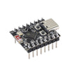
- ESP32-C3 4MB dev board (pre-soldered) - sensor node microcontroller
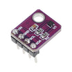
- GY-SHT45 temperature and humidity sensor module - I2C temperature and humidity sensing
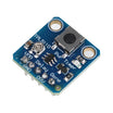
- TPL5110 low-power timer module - switches power fully off between readings
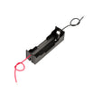
- 1 x 18650 battery holder with wires - powers the sensor node from a single 18650
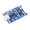
- TP4056 18650 charger board with protection - charging and protection for the 18650 cell
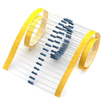
- Metal film resistor kit - two 100 kΩ resistors for the battery voltage divider
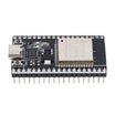
- ESP32 Dev Board 4MB CP2102 USB-C (38-pin) - ESP-NOW receiver and display controller
- MAX7219 4-in-1 dot matrix display module - LED matrix output for readings
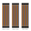
- Dupont jumper wires - wiring for both builds
External
- One 18650 Li-ion cell
- A USB power supply for the display
- A small enclosure with vents for the sensor node (so the SHT45 sees outside air)
Note: The TPL5110 module's trimmer sets the wake interval. Per the TPL5110 datasheet's resistor table, roughly 57 kΩ between DELAY and GND gives about 10 minutes. Check your board's silkscreen, because pin labels vary slightly between modules.
Step-by-Step Guide
Step 1 - Understand the power timer
Goal: See why this node lasts so long on one cell.
What to do: The TPL5110 sits between the battery and the ESP32-C3. When its timer expires it switches the output on through a MOSFET, the ESP32-C3 boots and does its work, then raises the DONE pin. The TPL5110 switches the output off on that edge and counts down again.
Between readings the only load is the timer itself, which the datasheet lists at about 35 nA typical, far less than any ESP32 deep sleep. The module's pushbutton forces a wake-up, which is handy for testing.
Expected result: You know the ESP32-C3 is fully unpowered between readings, so all state is lost and every wake-up starts from setup().
Step 2 - Wire the sensor node
Goal: Connect battery, timer, ESP32-C3, SHT45, and the battery divider.
What to do: Make these connections:
- 18650 holder to TP4056 B+ and B-
- TP4056 OUT+ to TPL5110 VDD, TP4056 OUT- to TPL5110 GND
- TPL5110 VOUT (the switched output) to ESP32-C3 5V pin, GND to ESP32-C3 GND
- TPL5110 DONE to ESP32-C3 GPIO3
- SHT45 VCC to 3V3, GND to GND, SDA to GPIO8, SCL to GPIO9
- Battery divider: TPL5110 VOUT to 100 kΩ to GPIO1 to 100 kΩ to GND
The divider sits after the TPL5110, so it only draws current while the node is awake. The board's 3.3 V regulator runs the ESP32-C3 from the cell; regulators differ in dropout between boards, so recharge through the TP4056 if the node stops reporting as the voltage falls.
Expected result: Pressing the TPL5110 button powers the ESP32-C3 briefly. Without firmware it simply stays on until the timer cycles.
Step 3 - Upload the sensor firmware
Goal: Read, broadcast, and switch off in well under a second.
What to do: Install Adafruit SHT4x Library from the Library Manager, select ESP32C3 Dev Module (set USB CDC On Boot to Enabled to see Serial output) and upload.
The node broadcasts on Wi-Fi channel 1 to the address FF:FF:FF:FF:FF:FF, so there is no MAC address to copy. Because broadcasts are not acknowledged, it sends three copies with a random wake-up ID that the display uses to drop duplicates.
If the board is still powered two seconds after pulsing DONE, it is running from USB, so it falls back to a 10-minute deep sleep. That makes testing at the bench easy.
Code:
// ShillehTek battery sensor node: ESP32-C3 + SHT45, powered through a TPL5110 timer
// TPL5110 switches power on -> read SHT45 + battery -> broadcast 3 ESP-NOW copies -> DONE
#include <WiFi.h>
#include <esp_now.h>
#include <esp_wifi.h>
#include <Wire.h>
#include <Adafruit_SHT4x.h>

const int SDA_PIN = 8, SCL_PIN = 9;
const int DONE_PIN = 3;           // to the TPL5110 DONE pin
const int VBAT_PIN = 1;           // middle of a 100k/100k divider on the switched supply
const uint8_t CHANNEL = 1;        // the display uses the same Wi-Fi channel
const uint8_t BROADCAST[6] = { 0xFF, 0xFF, 0xFF, 0xFF, 0xFF, 0xFF };
const uint32_t MAGIC = 0x35345453;   // "ST45"

struct __attribute__((packed)) Packet {
  uint32_t magic;
  uint32_t bootId;      // random per wake-up: lets the display drop the extra copies
  int16_t tempC100;     // temperature x100, INT16_MIN = sensor error
  uint16_t rh100;       // relative humidity x100
  uint16_t vbatMv;      // battery voltage in millivolts
};

Adafruit_SHT4x sht4 = Adafruit_SHT4x();

void powerOff() {
  // A rising edge on DONE tells the TPL5110 to cut power until the next interval
  unsigned long start = millis();
  while (millis() - start < 2000) {
    digitalWrite(DONE_PIN, HIGH);
    delay(1);
    digitalWrite(DONE_PIN, LOW);
    delay(1);
  }
  // Still alive, so we are on USB power for testing: deep sleep for 10 minutes instead
  esp_sleep_enable_timer_wakeup(10ULL * 60ULL * 1000000ULL);
  esp_deep_sleep_start();
}

void setup() {
  pinMode(DONE_PIN, OUTPUT);
  digitalWrite(DONE_PIN, LOW);
  Serial.begin(115200);

  Packet p;
  p.magic = MAGIC;
  p.bootId = esp_random();
  p.tempC100 = INT16_MIN;
  p.rh100 = 0;
  Wire.begin(SDA_PIN, SCL_PIN);
  if (sht4.begin()) {
    sht4.setPrecision(SHT4X_HIGH_PRECISION);
    sht4.setHeater(SHT4X_NO_HEATER);
    sensors_event_t hum, temp;
    sht4.getEvent(&hum, &temp);
    p.tempC100 = (int16_t)lroundf(temp.temperature * 100.0f);
    p.rh100 = (uint16_t)lroundf(hum.relative_humidity * 100.0f);
  }
  p.vbatMv = (uint16_t)(analogReadMilliVolts(VBAT_PIN) * 2);

  WiFi.mode(WIFI_STA);
  esp_wifi_set_channel(CHANNEL, WIFI_SECOND_CHAN_NONE);
  if (esp_now_init() == ESP_OK) {
    esp_now_peer_info_t peer = {};
    memcpy(peer.peer_addr, BROADCAST, 6);
    peer.channel = CHANNEL;
    peer.ifidx = WIFI_IF_STA;
    peer.encrypt = false;
    esp_now_add_peer(&peer);
    for (int i = 0; i < 3; i++) {        // broadcasts are not acknowledged: send 3 copies
      esp_now_send(BROADCAST, (const uint8_t *)&p, sizeof(p));
      delay(20);
    }
  }
  Serial.printf("T %.2f C  RH %.2f %%  VBAT %u mV  id %08lX\n",
                p.tempC100 / 100.0f, p.rh100 / 100.0f, (unsigned)p.vbatMv, (unsigned long)p.bootId);
  Serial.flush();
  powerOff();
}

void loop() {}
Expected result: On USB, the Serial Monitor prints one line like T 21.37 C RH 48.20 % VBAT 3970 mV id 0FD41F14, then the board goes quiet.
Step 4 - Wire the display
Goal: Connect the MAX7219 matrix to the ESP32's hardware SPI pins.
What to do: Connect the input end of the 4-in-1 module:
- VCC to ESP32 VIN (5V from USB), GND to GND
- DIN to GPIO23
- CLK to GPIO18
- CS to GPIO5
Most MAX7219 modules accept the ESP32's 3.3 V logic. If the display shows random dots, shorten the wires or add a level shifter on DIN, CLK and CS.

Expected result: Five wires between the ESP32 and the matrix, with the ESP32 powered over USB.
Step 5 - Upload the display firmware
Goal: Receive readings and cycle them on the matrix.
What to do: Install MD_Parola and MD_MAX72XX by majicDesigns from the Library Manager, select ESP32 Dev Module and upload.
The ESP-NOW callback only copies the packet and sets a flag; all display work happens in loop(). If your module shows mirrored or scrambled characters, change FC16_HW to GENERIC_HW or PAROLA_HW.
Code:
// ShillehTek ESP-NOW display: ESP32 + MAX7219 4-in-1 matrix shows the latest SHT45 reading
#include <WiFi.h>
#include <esp_now.h>
#include <esp_wifi.h>
#include <MD_Parola.h>
#include <MD_MAX72xx.h>
#include <SPI.h>

#define HARDWARE_TYPE MD_MAX72XX::FC16_HW
const uint8_t MAX_DEVICES = 4;
const uint8_t CS_PIN = 5;              // DIN -> GPIO23, CLK -> GPIO18 (hardware SPI)
const uint8_t CHANNEL = 1;             // must match the sensor node
const uint32_t MAGIC = 0x35345453;     // "ST45"
const unsigned long STALE_MS = 25UL * 60UL * 1000UL;   // 2.5 x a 10-minute interval
const uint16_t PAGE_MS = 3000;

struct __attribute__((packed)) Packet {
  uint32_t magic;
  uint32_t bootId;
  int16_t tempC100;
  uint16_t rh100;
  uint16_t vbatMv;
};

MD_Parola disp = MD_Parola(HARDWARE_TYPE, CS_PIN, MAX_DEVICES);
portMUX_TYPE rxMux = portMUX_INITIALIZER_UNLOCKED;
volatile bool rxFlag = false;
Packet rxPacket;                       // written by the callback, read by loop()

Packet latest;
bool haveData = false;
uint32_t lastBootId = 0;
unsigned long lastRxMs = 0;
uint32_t readings = 0;
uint8_t page = 0;
char text[16];

// Runs in the Wi-Fi task: copy the data and leave. No display work here.
void onRecv(const esp_now_recv_info_t *info, const uint8_t *data, int len) {
  if (len != (int)sizeof(Packet)) return;
  Packet p;
  memcpy(&p, data, sizeof(p));
  if (p.magic != MAGIC) return;
  portENTER_CRITICAL(&rxMux);
  rxPacket = p;
  rxFlag = true;
  portEXIT_CRITICAL(&rxMux);
}

// True for a new reading, false for the extra copies of the same wake-up
bool acceptPacket(const Packet &p) {
  if (haveData && p.bootId == lastBootId) return false;
  lastBootId = p.bootId;
  latest = p;
  haveData = true;
  return true;
}

void makePage(uint8_t n, char *out, size_t len) {
  if (!haveData) {
    snprintf(out, len, "WAIT");
    return;
  }
  bool sensorError = latest.tempC100 == INT16_MIN;
  switch (n) {
    case 0:
      if (sensorError) snprintf(out, len, "ERR");
      else snprintf(out, len, "%.1fC", latest.tempC100 / 100.0f);
      break;
    case 1:
      if (sensorError) snprintf(out, len, "ERR");
      else snprintf(out, len, "%u%%", (unsigned)((latest.rh100 + 50) / 100));
      break;
    case 2:
      snprintf(out, len, "%.2fV", latest.vbatMv / 1000.0f);
      break;
    default:
      snprintf(out, len, "OLD");      // shown only when no reading for STALE_MS
      break;
  }
}

void setup() {
  Serial.begin(115200);
  disp.begin();
  disp.setIntensity(2);
  makePage(0, text, sizeof(text));                // "WAIT" until the first reading
  disp.displayText(text, PA_CENTER, 0, PAGE_MS, PA_PRINT, PA_NO_EFFECT);

  WiFi.mode(WIFI_STA);
  esp_wifi_set_channel(CHANNEL, WIFI_SECOND_CHAN_NONE);
  if (esp_now_init() != ESP_OK) {
    Serial.println("ESP-NOW init failed");
    return;
  }
  esp_now_register_recv_cb(onRecv);
  Serial.printf("Display ready on channel %u, MAC %s\n", CHANNEL, WiFi.macAddress().c_str());
}

void loop() {
  if (rxFlag) {
    Packet p;
    portENTER_CRITICAL(&rxMux);
    p = rxPacket;
    rxFlag = false;
    portEXIT_CRITICAL(&rxMux);
    if (acceptPacket(p)) {
      lastRxMs = millis();
      readings++;
      if (p.tempC100 == INT16_MIN) {
        Serial.printf("#%lu  sensor error  %u mV\n", (unsigned long)readings, (unsigned)p.vbatMv);
      } else {
        Serial.printf("#%lu  %.2f C  %.2f %%RH  %u mV\n", (unsigned long)readings,
                      p.tempC100 / 100.0f, p.rh100 / 100.0f, (unsigned)p.vbatMv);
      }
    }
  }

  if (disp.displayAnimate()) {         // true when the current page has been shown
    bool stale = haveData && millis() - lastRxMs > STALE_MS;
    uint8_t pages = !haveData ? 1 : (stale ? 4 : 3);
    page = (page + 1) % pages;
    makePage(page, text, sizeof(text));
    disp.displayText(text, PA_CENTER, 0, PAGE_MS, PA_PRINT, PA_NO_EFFECT);
  }
}
Expected result: The matrix shows WAIT until the first packet arrives, then cycles readings such as 21.4C, 48% and 3.97V every three seconds. Press the TPL5110 button on the node to send a reading on demand.
Step 6 - Set the wake interval
Goal: Choose how often the node reports.
What to do: With the battery removed, measure the resistance between the TPL5110 DELAY pin and GND while turning the trimmer. Per the datasheet table, about 57 kΩ gives roughly 10 minutes, larger values give longer intervals (up to about two hours) and smaller values shorter ones.
Time a few cycles with the display's Serial output to confirm. If you change the interval a lot, update STALE_MS in the display sketch to about 2.5 times the new interval.
Expected result: New readings arrive at your chosen interval. If the node stops reporting for 25 minutes, the display adds an OLD page.
Step 7 - Estimate battery life
Goal: Know when to recharge.
What to do: Watch the voltage page over a few days. Each wake-up lasts well under a second and the timer's standby draw is tiny, so at a 10-minute interval a 2,500 mAh cell typically lasts many months. Your exact figure depends on the board's regulator and how quickly the ESP32-C3 boots. Recharge through the TP4056 when the display shows about 3.5 V.
Expected result: A steady, slowly falling voltage trend and a node that keeps reporting for months between charges.
Conclusion
You built an ESP32-C3 sensor node that reads an SHT45, broadcasts over ESP-NOW, and lets a TPL5110 cut its power between readings, plus an ESP32 display that drops duplicate packets, cycles temperature, humidity and battery voltage on a MAX7219 matrix, and warns when data goes stale. Add more nodes by giving each packet a node number and adding a page per node.
Want the exact parts used in this build? Grab them from ShillehTek.com. If you want help customizing this project or building something for your product, check out our IoT consulting services.
Photo credit: Images referenced from Hendra Kusumah on Hackster.io, which served as the reference for this version.
Credits
All photos and images in this tutorial are credited to Hendra Kusumah on Hackster.io. The original guide by Hendra Kusumah served as the reference for this ShillehTek version. We thank them for their excellent work in the maker community.