

Project Overview
Arduino Uno + water level sensor tank monitor: Read liquid level as an analog value, smooth it, convert it to a percentage, display it on a 16x2 I2C LCD, and trigger an RGB status light plus a full-tank buzzer alarm.
The sensor uses exposed traces to measure conductivity, so raw readings can jump around. Averaging multiple samples per update (20 readings in this build) makes the percentage stable and usable.
- Time: ~45 minutes
- Skill level: Beginner
- What you will build: A tank monitor showing fill percentage live, with an RGB status light and a 99%-full alarm.

Parts List
From ShillehTek
- Arduino Uno R3 Super Starter Kit - includes the water level sensor, RGB LED, and resistors
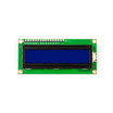
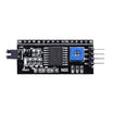
- LCD1602 Display + PCF8574 I2C backpack - the percentage readout over I2C (SDA/SCL)
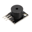
- KY-006 Passive Buzzer - full-tank alarm output
- 400-Point Breadboard - prototyping the circuit
- Dupont Jumper Wires - wiring connections
External
- A glass of water for testing
Note: These sensors read by conductivity between the exposed traces, so raw readings can jump around. Averaging 20 samples per reading turns a jittery number into a stable one.
Step-by-Step Guide
Step 1 - Wire sensor, LCD, RGB LED, and buzzer
Goal: Connect all four subsystems to the Arduino Uno.
What to do: Wire the water sensor: + to 5V, - to GND, S to A0. Wire the I2C LCD (address 0x27): SDA to A4 and SCL to A5. Wire the RGB LED through 220 ohm resistors: green to D8, blue to D9, red to D10. Wire the buzzer to D2.
Only the sensors gold fingers should touch water. Keep the sensor board and the Arduino above the waterline.

Expected result: The hardware is ready for a dunk test.
Step 2 - Calibrate dry and full readings
Goal: Map raw analog readings to 0 to 100% accurately for your specific sensor.
What to do: Print raw analogRead(A0) values and note the reading when the sensor is dry (often near 0) and when submerged to the max line (often around 650, not 1023). Use those two values as the endpoints for map() so the displayed percentage matches your real setup.
Expected result: You have real dry and full bounds for your unit.
Step 3 - Upload the monitor sketch
Goal: Smooth the sensor value, convert it to a percentage, show it on the LCD, and drive the RGB and buzzer outputs.
Code:
#include <LiquidCrystal_I2C.h>
LiquidCrystal_I2C lcd(0x27, 16, 2);

const int SENSOR = A0;
const int BUZZER = 2;
const int R = 10, B = 9, G = 8;
const int DRY = 0, FULL = 650;    // your Step 2 calibration

void setup() {
  lcd.init();
  lcd.backlight();
  pinMode(BUZZER, OUTPUT);
  pinMode(R, OUTPUT); pinMode(G, OUTPUT); pinMode(B, OUTPUT);
}

void loop() {
  long sum = 0;                    // average 20 readings
  for (int i = 0; i < 20; i++) { sum += analogRead(SENSOR); delay(10); }
  int pct = constrain(map(sum / 20, DRY, FULL, 0, 100), 0, 100);

  lcd.setCursor(0, 0);
  lcd.print("Water: ");
  lcd.print(pct);
  lcd.print("%   ");

  digitalWrite(G, pct < 60);                 // green: safe
  digitalWrite(B, pct >= 60 && pct < 99);    // blue: filling
  digitalWrite(R, pct >= 99);                // red: FULL

  if (pct >= 99) tone(BUZZER, 2000, 300);    // alarm at the brim

  delay(300);
}
Expected result: Dip the sensor and watch the percentage climb. At 99% the RGB turns red and the buzzer chirps.
Step 4 - Mount it on a real tank
Goal: Move from a glass-of-water test to a useful monitor.
What to do: Mount the sensor at the height that matters, such as the almost-full zone of a reservoir, sump pit, or humidifier tank. For deeper tanks, you can pair contact sensing near the top with a waterproof ultrasonic sensor for full-depth measurement.
Expected result: A tank overflow guard you can actually deploy.
Conclusion
You built an Arduino Uno water level sensor monitor that averages noisy analog readings, maps them to a reliable percentage, displays the value on an I2C LCD, and triggers an RGB status light plus a 99% full alarm buzzer.
Want the exact parts used in this build? Grab them from ShillehTek.com. If you want help customizing this project or building something for your product, check out our IoT consulting services.
Credits: Photos and reference concept adapted from Rachana Jain on Hackster.io.





.png?v=25000753014097803521791168436)

.png?v=68677308723310773341791168436)


