

Project Overview
Arduino UNO + HMC5883L compass sensor: In this build you connect an HMC5883L 3-axis magnetometer to an Arduino UNO over I2C, read live X/Y/Z magnetic field values, and display them on both the Serial Monitor and a 16x2 LCD.
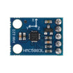
The HMC5883L is the same class of sensor used for compass direction in phones. This module runs from 3V to 5V, includes an onboard regulator, and needs only two I2C signal wires.
- Time: About 1 hour
- Skill level: Beginner
- What you will build: A live 3-axis compass readout on an LCD and the serial monitor.

Parts List
From ShillehTek
- HMC5883L GY-273 Pre-Soldered 3-Axis Magnetometer Compass Module - the I2C compass sensor module used for X/Y/Z field readings
- Arduino Nano V3 - or any Arduino UNO-compatible board to read I2C data and drive the LCD
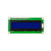
- LCD1602 16x2 Display Module - displays the X/Y/Z values without needing the computer
- 830-Point Solderless Breadboard - for building the circuit without soldering
- 120pcs 20cm Dupont Jumper Wires - for wiring the sensor, LCD, and power rails
External
- 10K potentiometer (LCD contrast)
- USB cable for the Arduino
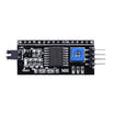
Note: Prefer less wiring? A PCF8574 I2C backpack replaces the LCD's parallel wiring and the contrast pot with two I2C wires.
Step-by-Step Guide
Step 1 - Know the sensor pins and what it reports
Goal: Understand what the HMC5883L reports and which pins you actually need.
What to do: Review the key specs: 3V to 5V supply and IO, standard I2C protocol, a measuring range of ±1.3 to 8 gauss, and a small footprint. The sensor measures magnetic field strength along three axes, which lets you compute a compass heading or detect nearby magnetized objects.

Expected result: You know the five pins: VCC, GND, SCL, SDA, and the optional data-ready output DRDY.
Step 2 - Wire the sensor, LCD, and contrast potentiometer
Goal: Complete the full circuit on a breadboard.
What to do: Make these connections:
HMC5883L:  VCC -> 5V   GND -> GND   SCL -> A5   SDA -> A4

LCD 16x2:  VSS -> GND      VDD -> 5V     RS -> 12   RW -> GND
           E  -> 11        D4 -> 5       D5 -> 4
           D6 -> 3         D7 -> 2
           A (backlight+) -> 5V   K (backlight-) -> GND

10K pot:   one end -> 5V, other end -> GND, wiper -> LCD V0 (contrast)

Expected result: Sensor on the I2C pins, LCD on the digital pins, and the pot wired to the LCD contrast pin.
Step 3 - Power up and check the LCD contrast
Goal: Verify the hardware before uploading code.
What to do: Plug the Arduino into your computer over USB. The LCD backlight should light immediately. Twist the potentiometer until you can see the character cells faintly.

Expected result: A powered board and visible LCD backlight, with contrast adjusted so text will be readable.
Step 4 - Confirm the required Arduino libraries
Goal: Ensure the IDE has what it needs to compile.
What to do: The sketch relies on the Wire library (I2C) and LiquidCrystal (LCD). Both ship with the modern Arduino IDE. If your IDE is missing them, add the library files to your Arduino libraries folder before compiling.

Expected result: The IDE compiles sketches with Wire and LiquidCrystal includes without errors.
Step 5 - Upload the sketch to read X/Y/Z and print to LCD
Goal: Read raw X/Y/Z values from the compass and display them.
What to do: Upload a sketch that configures continuous-measurement mode, then reads six bytes per sample from the data registers and prints the results to Serial and the LCD. The core read loop looks like this:
#include <Wire.h>
#include <LiquidCrystal.h>

#define HMC_ADDR 0x1E  // I2C 7-bit address of HMC5883L

LiquidCrystal lcd(12, 11, 5, 4, 3, 2);

void setup() {
  Serial.begin(9600);
  Wire.begin();
  lcd.begin(16, 2);

  Wire.beginTransmission(HMC_ADDR);
  Wire.write(0x02);      // mode register
  Wire.write(0x00);      // continuous measurement mode
  Wire.endTransmission();
}

void loop() {
  int x, y, z;

  Wire.beginTransmission(HMC_ADDR);
  Wire.write(0x03);      // start of data registers
  Wire.endTransmission();

  Wire.requestFrom(HMC_ADDR, 6);
  if (6 <= Wire.available()) {
    x = Wire.read() << 8 | Wire.read();  // X MSB, LSB
    z = Wire.read() << 8 | Wire.read();  // Z MSB, LSB (register order!)
    y = Wire.read() << 8 | Wire.read();  // Y MSB, LSB
  }

  Serial.print("X: "); Serial.print(x);
  Serial.print("  Y: "); Serial.print(y);
  Serial.print("  Z: "); Serial.println(z);

  lcd.setCursor(0, 0);
  lcd.print("X:"); lcd.print(x);
  lcd.print(" Y:"); lcd.print(y);
  lcd.setCursor(0, 1);
  lcd.print("Z:"); lcd.print(z);

  delay(250);
}

Expected result: The sketch uploads successfully and the LCD starts showing changing numbers.
Step 6 - Rotate the sensor and verify axis behavior
Goal: Confirm each axis responds correctly to rotation.
What to do: Rotate the breadboard and watch the readings. Rotate around the X axis and X stays roughly constant while Y and Z change. Rotate around Y and Y holds steady while the others change. Rotate around Z and Z holds steady. This is expected for a 3-axis magnetometer.


Expected result: All three axes respond as described, on both the Serial Monitor and the LCD.
Step 7 - Confirm your module I2C address (HMC5883L vs QMC5883L)
Goal: Identify the chip variant if the module does not show up at the expected address.
What to do: Many GY-273 style boards actually carry the QMC5883L, a licensed variant that uses I2C address 0x0D instead of 0x1E. Run an I2C scanner: address 0x1E indicates an HMC5883L, while 0x0D indicates a QMC5883L. If you have the QMC variant, switch to a QMC5883L library (such as Mecha_QMC5883L).
Expected result: You know which address your module uses, and you can select compatible code or a library for the detected chip.
Conclusion
You connected an HMC5883L 3-axis magnetometer to an Arduino over I2C, streamed live X/Y/Z magnetic readings to the Serial Monitor, and displayed them on a 16x2 LCD. From here you can compute a compass heading using atan2(Y, X), build a digital compass for a robot, or detect magnets and ferrous metal near the sensor.
Want the exact parts used in this build? Grab them from ShillehTek.com. If you want help customizing this project or building something for your product, check out our IoT consulting services.
Photo credit: images referenced from Instructables (Mybotic).





.png?v=25000753014097803521791168436)

.png?v=68677308723310773341791168436)


