

Project Overview
DIY Arduino Robot Arm with Smartphone Control: Build an Arduino Uno robot arm using an HC-05 Bluetooth module so you can control six servos from an Android phone and record movements to replay them automatically.
The build uses a 3D-printed frame (or a pre-made arm platform), three high-torque servos for the load-bearing joints, and three micro servos for the wrist and gripper. The phone app provides one slider per joint plus Save/Run controls to store poses and loop them like a miniature industrial robot.
- Time: A weekend (printing + assembly + wiring)
- Skill level: Intermediate
- What you will build: A smartphone-controlled robotic arm that can memorize a sequence of positions and loop them automatically.

Parts List
From ShillehTek
- MG995 Metal Gear Servo (12kg High Torque) - you need 3 of this class (MG996R-equivalent) for the waist, shoulder, and elbow
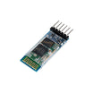
- HC-05 6-Pin Bluetooth Module - Bluetooth link between the phone app and Arduino
- Arduino Uno R3 - main controller for six servos and Bluetooth commands
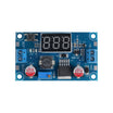
- LM2596 Adjustable Step-Down Converter - provides a strong 5V rail for servo power
- Dupont Jumper Wires - quick connections for signals and module wiring
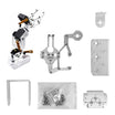
- Prefer a no-printing shortcut? The 3DOF DIY Robot Arm Kit with 3x MG995 Servos gives you a ready-made arm platform to run the same code and app on.
External
- 3 x SG90/MG90S micro servos (wrist roll, wrist pitch, gripper)
- 3D-printed arm parts (STLs from the original guide) or an arm frame of your own
- 5V, 2A or higher supply for the servos (the LM2596 fed from a 12V adapter works well)
- An Android phone for the control app
- Resistors for a simple 1k/2k voltage divider to protect the HC-05 RX pin
Note: Never power six servos from the Arduino's 5V pin. Stalled MG996R-class servos can pull well over an amp each. Give the servos their own 5V rail and tie the grounds together.
Step-by-Step Guide
Step 1 - Understand the Arm
Goal: Know what the six servos do.
What to do: The arm has five degrees of freedom plus a gripper. The three big joints (waist rotation, shoulder, and elbow) carry real load, so they use metal-gear MG996R-class servos. The wrist roll, wrist pitch, and gripper barely lift anything, so light SG90 micro servos handle those.
The frame was modeled in CAD and 3D-printed; the STLs are freely available in the original guide.


Expected result: You know which servo goes where and why.
Step 2 - Print and Assemble the Frame
Goal: Build the mechanical arm.
What to do: Print the parts (PLA at standard settings is fine), then assemble joint by joint from the base up. Bolt the waist servo into the base, attach the rotating platform to its horn, then work up through shoulder, elbow, and wrist, seating each servo before closing its joint.
Center every servo (90 degrees) before screwing horns down, or the arm's range will be lopsided. A rubber band looped across the shoulder joint helps the shoulder servo fight gravity on the longest lever.


Expected result: A finished arm that moves freely by hand at every joint.
Step 3 - Wire the Electronics
Goal: Connect six servos, the HC-05, and power.
What to do: Servo signal wires go to Arduino pins D5 to D10 (waist through gripper). Wire the HC-05 as VCC to 5V, GND to GND, TX to D3, and RX to D4 through a simple 1k/2k voltage divider (the module's RX pin is 3.3V logic).
Set your LM2596 to 5.0V and feed every servo's power lead from it, not from the Arduino. Tie the converter's ground to the Arduino's GND so signals share a reference.

Expected result: Electronics complete, with a servo power rail that will not brown out the Arduino.
Step 4 - Load the Code
Goal: Let the phone command every joint.
What to do: The sketch keeps a Servo object per joint and parses slider messages arriving over Bluetooth. The condensed control loop looks like this. The complete sketch (including smooth-speed moves and the record/replay logic) is on the original guide.
Code:
#include <SoftwareSerial.h>
#include <Servo.h>

Servo servo01, servo02, servo03, servo04, servo05, servo06;
SoftwareSerial Bluetooth(3, 4);   // HC-05 TX -> D3, RX -> D4 (via divider)

int servo1Pos = 90, servo2Pos = 150, servo3Pos = 35,
    servo4Pos = 140, servo5Pos = 85, servo6Pos = 80;
String dataIn = "";

void setup() {
  servo01.attach(5);   // waist
  servo02.attach(6);   // shoulder
  servo03.attach(7);   // elbow
  servo04.attach(8);   // wrist roll
  servo05.attach(9);   // wrist pitch
  servo06.attach(10);  // gripper
  Bluetooth.begin(38400);
  Bluetooth.setTimeout(1);
  delay(20);
}

void loop() {
  if (Bluetooth.available() > 0) {
    dataIn = Bluetooth.readString();       // e.g. "s1120" = waist to 120 deg
    if (dataIn.startsWith("s1")) {
      servo1Pos = dataIn.substring(2).toInt();
      servo01.write(servo1Pos);
    }
    // ...same pattern for s2..s6, plus speed,
    // SAVE (record step) and RUN (replay saved steps)
  }
}
Expected result: The arm twitches to its home pose on boot and responds to Bluetooth commands.
Step 5 - Drive It from the App
Goal: Control, then automate, the arm.
What to do: Pair your phone with the HC-05 (PIN 1234), open the control app from the original guide (built with MIT App Inventor, source included), and connect. Each slider drives one joint live, and the speed slider scales how fast moves execute.
The Save button records poses. Pose the arm, tap Save, pose it again, tap Save, then hit Run and the arm replays the whole recorded sequence in a loop. Reset clears the memory for a new routine.

Expected result: A robot arm that follows live slider control and can replay saved motion sequences automatically.
Conclusion
You built an Arduino Uno robot arm with an HC-05 Bluetooth module that can be driven from a phone and can record and replay servo positions. This combines multi-servo control, proper servo power design, wireless commands, and simple motion automation using saved steps.
Want the exact parts used in this build? Grab them from ShillehTek.com. If you want help customizing this project or building something for your product, check out our IoT consulting services.
Credits: Photos and original build concept referenced from Dejan of HowToMechatronics and the Hackster.io repost by Webotricks.





.png?v=25000753014097803521791168436)

.png?v=68677308723310773341791168436)


