

Project Overview
Arduino Nano + LCD1602 (I2C) Stopwatch: Build a responsive stopwatch that shows MM:SS.hh on a 16x2 LCD with Start/Stop, Lap, and Reset, using millis() arithmetic for accurate timekeeping without delay().
This project uses three buttons, two status LEDs, and a buzzer click for button feedback. The key idea is timestamp-based timing: every display update is derived from millis(), so the stopwatch stays accurate while remaining responsive to inputs.
- Time: ~45 minutes
- Skill level: Beginner
- What you will build: A lap-capable stopwatch with MM:SS.hh resolution, debounced buttons with audible clicks, and running/stopped indicator LEDs.

Parts List
From ShillehTek
- Arduino Nano V3.0 Pre-Soldered - the main microcontroller board for the stopwatch
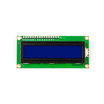
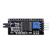
- LCD1602 Display + PCF8574 I2C backpack - shows time and lap on a 16x2 display over I2C
- Tactile Button Kit - Start/Stop, Lap, Reset inputs
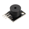
- KY-006 Passive Buzzer - button click feedback
- Resistor Kit - 220Ω resistors for the LEDs
- 400-Point Breadboard - easy prototyping
- Dupont Jumper Wires - quick connections between parts
External
- One green LED and one red LED - running/stopped indicators
Note: The trick to an accurate stopwatch is to store timestamps, not to count. Record millis() when you press Start; the elapsed time is always "now minus start" plus whatever was accumulated before the last stop. No drift, no matter how slow the display loop is.
Step-by-Step Guide
Step 1 - Wire the Panel
Goal: Three inputs, three outputs, one display.
What to do: Wire the buttons from A0 (Start/Stop), A1 (Lap), and A2 (Reset) to GND. The sketch uses internal pull-ups, so you do not need external resistors for the buttons.
Wire the green LED: D8 → 220Ω → LED → GND. Wire the red LED: D9 → 220Ω → LED → GND. Connect the buzzer to D13. Connect the LCD via I2C on A4/A5.

Expected result: A stopwatch front panel on a breadboard.
Step 2 - Plan the Behavior
Goal: Decide what each button does in each state.
What to do: Start/Stop toggles running. Lap captures the current time into the second line without stopping. Reset only works while stopped so you cannot wipe a running time by accident.
Use the LEDs as state indicators: green LED means running, red LED means stopped. Every press clicks the buzzer so you know it registered.
Expected result: A behavior plan you can check the code against.
Step 3 - Upload the Sketch
Goal: Implement debounced buttons and timestamp-based timekeeping with millis().
What to do: Paste the sketch below into the Arduino IDE, select your board and port, and upload.
Code:
#include <LiquidCrystal_I2C.h>
LiquidCrystal_I2C lcd(0x27, 16, 2);

const int BTN_START = A0, BTN_LAP = A1, BTN_RESET = A2;
const int LED_RUN = 8, LED_STOP = 9, BUZZ = 13;

bool running = false;
unsigned long startMs = 0, elapsed = 0, lapMs = 0;

bool pressed(int pin) {                       // debounced press + click, waits for release
  if (digitalRead(pin) == LOW) {
    delay(25);
    if (digitalRead(pin) == LOW) {
      tone(BUZZ, 1200, 30);
      while (digitalRead(pin) == LOW);
      return true;
    }
  }
  return false;
}

void printTime(int col, int row, unsigned long ms) {
  unsigned long hund = (ms / 10) % 100, sec = (ms / 1000) % 60, min = ms / 60000;
  char buf[12];
  sprintf(buf, "%02lu:%02lu.%02lu", min, sec, hund);   // MM:SS.hh
  lcd.setCursor(col, row); lcd.print(buf);
}

void setup() {
  pinMode(BTN_START, INPUT_PULLUP); pinMode(BTN_LAP, INPUT_PULLUP); pinMode(BTN_RESET, INPUT_PULLUP);
  pinMode(LED_RUN, OUTPUT); pinMode(LED_STOP, OUTPUT);
  lcd.init(); lcd.backlight();
  lcd.setCursor(0, 0); lcd.print("TIME");
  lcd.setCursor(0, 1); lcd.print("LAP");
}

void loop() {
  if (pressed(BTN_START)) {
    if (running) { elapsed += millis() - startMs; running = false; }   // stop: bank the time
    else         { startMs = millis(); running = true; }               // start: new segment
  }
  if (pressed(BTN_LAP) && running)  lapMs = elapsed + (millis() - startMs);
  if (pressed(BTN_RESET) && !running) { elapsed = 0; lapMs = 0; }

  unsigned long now = elapsed + (running ? millis() - startMs : 0);
  printTime(6, 0, now);
  printTime(6, 1, lapMs);
  digitalWrite(LED_RUN, running);
  digitalWrite(LED_STOP, !running);
}
Expected result: Accurate time on line 1, last lap on line 2, green while running, red when stopped, and a click per press.
Step 4 - Check It Against Your Phone
Goal: Validate the timing behavior and understand clock accuracy.
What to do: Start both stopwatches together and compare after five minutes. They should agree to within a fraction of a second. The ceramic resonator on a Nano is typically accurate to about 0.1% to 0.5%, so a few hundred milliseconds over five minutes is normal.
If you need lab-grade timing, swap to a board with a crystal or add a DS3231 RTC.
Expected result: Confidence in the millis() approach and a feel for your board's clock accuracy.
Step 5 - Upgrades
Goal: Extend the project while keeping the same timestamp-based core.
What to do: Store multiple laps in an array and scroll through them, add a countdown mode, or trigger Start/Stop from a light gate or pressure pad for sprint timing.
Expected result: A timing tool that better fits your use case.
Conclusion
This Arduino Nano and LCD1602 stopwatch demonstrates the most important habit in Arduino timing projects: keep time with timestamps, not delays. With millis()-based arithmetic, the display stays accurate while buttons, LEDs, and the buzzer remain responsive.
Want the exact parts used in this build? Grab them from ShillehTek.com. If you want help customizing this project or building something for your product, check out our IoT consulting services.
Photo and circuit references are credited to Mohammad Sohail on Hackster.io.






.png?v=25000753014097803521791168436)

.png?v=68677308723310773341791168436)


