

Project Overview
Arduino Nano + LCD1602 (I2C) Kitchen Timer: Build a knob-set countdown timer where an Arduino Nano reads a potentiometer, shows minutes and seconds on an LCD1602, and triggers a buzzer alarm when time reaches zero.
This project uses a simple state machine (SETTING, RUNNING, ALARM) so the timer behaves like a finished appliance: set time, press Start, watch a blinking colon during the countdown, then reset to stop the alarm.
- Time: ~1 hour
- Skill level: Beginner-Intermediate
- What you will build: A kitchen timer with knob-set duration, Start/Reset buttons, an LCD countdown, and a state-machine core you can reuse.

Parts List
From ShillehTek
- Arduino Nano V3.0 Pre-Soldered - main microcontroller running the timer state machine
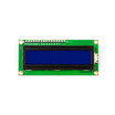
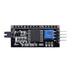
- LCD1602 Display + PCF8574 I2C backpack - displays the countdown over I2C (the original design used a TM1637 4-digit display)
- Tactile Button Kit - Start and Reset inputs
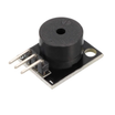
- KY-006 Passive Buzzer - audible alarm when the timer reaches zero
- Uno Starter Kit - source of the 10kΩ potentiometer (or use any compatible potentiometer)
- 400-Point Breadboard - quick prototyping of the circuit
- Dupont Jumper Wires - wiring between the Nano, LCD, buttons, buzzer, and potentiometer
External
- None
Note: The knob sets time in 30-second steps up to 60 minutes. Quantizing the potentiometer reading is what makes the knob feel like a real dial instead of a jittery number.
Step-by-Step Guide
Step 1 - Wire the Front Panel
Goal: Connect the knob (potentiometer), two buttons, buzzer, and I2C LCD to the Arduino Nano.
What to do: Connect the potentiometer wiper to A0, and the two outer legs to 5V and GND. Wire the Start button to D4 and the Reset button to D5, with the other side of each button to GND (you will use INPUT_PULLUP in code). Connect the buzzer signal to D6. Connect the I2C LCD to A4 (SDA) and A5 (SCL).

Expected result: Your control panel is wired and ready for firmware.
Step 2 - Think in States
Goal: Define the timer behavior as a state machine before coding.
What to do: Keep the timer in exactly one state at a time: SETTING (knob edits the time), RUNNING (counts down each second), or ALARM (buzzer and flashing zeros). The buttons move between states; nothing else does. Sketch the states and the Start/Reset transitions so the code stays simple.
Expected result: A small state diagram with arrows labeled Start and Reset.
Step 3 - Upload the Sketch
Goal: Load the state machine firmware onto the Arduino Nano.
Code:
#include <LiquidCrystal_I2C.h>
LiquidCrystal_I2C lcd(0x27, 16, 2);

const int POT = A0, START = 4, RESET = 5, BUZZ = 6;
enum State { SETTING, RUNNING, ALARM };
State state = SETTING;

long secondsLeft = 0;
unsigned long lastTick = 0;

void showTime(long s, bool colon) {
  lcd.setCursor(4, 1);
  if (s / 60 < 10) lcd.print('0');
  lcd.print(s / 60); lcd.print(colon ? ':' : ' ');
  if (s % 60 < 10) lcd.print('0');
  lcd.print(s % 60);
}

void setup() {
  pinMode(START, INPUT_PULLUP); pinMode(RESET, INPUT_PULLUP);
  lcd.init(); lcd.backlight();
}

void loop() {
  if (digitalRead(RESET) == LOW) { state = SETTING; noTone(BUZZ); delay(200); }

  switch (state) {
    case SETTING: {
      // knob -> 0..60 min in 30 s steps
      secondsLeft = (map(analogRead(POT), 0, 1023, 0, 120)) * 30L;
      lcd.setCursor(0, 0); lcd.print("Set time:  START");
      showTime(secondsLeft, true);
      if (digitalRead(START) == LOW && secondsLeft > 0) {
        state = RUNNING; lastTick = millis(); delay(200);
      }
      break;
    }
    case RUNNING: {
      lcd.setCursor(0, 0); lcd.print("Counting down...");
      if (millis() - lastTick >= 1000) {
        lastTick += 1000;
        secondsLeft--;
        if (secondsLeft <= 0) state = ALARM;
      }
      showTime(secondsLeft, (millis() / 500) % 2);   // blinking colon
      break;
    }
    case ALARM: {
      lcd.setCursor(0, 0); lcd.print("   TIME'S UP!   ");
      showTime(0, (millis() / 250) % 2);
      tone(BUZZ, (millis() / 250) % 2 ? 2000 : 0);   // chirping alarm
      break;
    }
  }
}
What to do: Upload the sketch, dial in 2 minutes, and press Start.
Expected result: A countdown on the LCD with a blinking colon, then an alarm that continues until you press Reset.
Step 4 - Appliance Polish (Optional)
Goal: Identify next refinements you can add after the core timer works.
What to do: If you want to extend the project, you can add a pause feature (Start toggles RUNNING to a PAUSED state), save the last duration, or add preset buttons (for example 3/5/10 minutes). Mount the potentiometer and buttons through an enclosure lid to make it a gift-worthy gadget.
Expected result: A solid baseline timer that is easy to expand because the behavior is organized as states and transitions.
Conclusion
You built an Arduino Nano kitchen timer that reads a potentiometer, shows a countdown on an LCD1602 over I2C, and sounds a buzzer alarm at zero. The key takeaway is the state-machine structure (SETTING, RUNNING, ALARM), which scales cleanly to almost any button-driven embedded device.
Want the exact parts used in this build? Grab them from ShillehTek.com. If you want help customizing this project or building something for your product, check out our IoT consulting services.
Credits: All photos and images in this tutorial are credited to Mirko Pavleski on Hackster.io. The original guide by Mirko Pavleski served as the reference for this ShillehTek version.






.png?v=25000753014097803521791168436)

.png?v=68677308723310773341791168436)


