

Project Overview
Arduino Nano + LCD1602 voltmeter: Build a DC voltmeter that reads an Arduino Nano analog pin and displays the result on an LCD1602, then extend the input range to about 0 to 50 V using a simple two-resistor voltage divider.
The Arduino already contains a voltmeter: its 10-bit ADC reads 0 to 5 V in 1024 steps. This project puts that reading on an LCD, then uses a divider so it can safely measure batteries, power supplies, and solar panels up to 50 V. You will also learn how the ADC maps volts to counts, why averaging matters, and how to calibrate against the reference voltage.
- Time: ~40 minutes
- Skill level: Beginner
- What you will build: A bench voltmeter with a 16x2 readout, selectable range, over-range warning, and two-point calibration.

Parts List
From ShillehTek
- Arduino Nano V3.0 Pre-Soldered - the microcontroller board that reads the ADC and drives the display
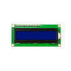
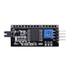
- LCD1602 Display + PCF8574 I2C backpack - shows the measured voltage over I2C
- Resistor Kit - 100kΩ + 10kΩ (or 30kΩ + 10kΩ) for the voltage divider
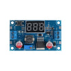
- LM2596 Adjustable Buck Converter - adjustable voltage source to measure and calibrate against
- 400-Point Breadboard - for prototyping the divider and wiring
- Dupont Jumper Wires - for connections between the Nano and the LCD
External
- Two test leads or alligator clips
- A known-good multimeter for the calibration step
- Optional: 0.1 µF capacitor (for stabilizing the ADC reading on A3)
Note: Never put more than 5 V directly on an Arduino pin. The divider makes higher voltages safe: a 100k/10k pair divides by 11 (about 0 to 55 V range, about 54 mV steps), while a 30k/10k pair divides by 4 (0 to 20 V, about 20 mV steps). Pick the ratio that fits what you measure most.
Step-by-Step Guide
Step 1 - Start with the bare ADC (0 to 5 V)
Goal: Read a voltage directly.
What to do: Wire the LCD to A4/A5 (SDA/SCL), 5V, and GND. Connect a jumper from A3 to the 3.3V pin, and read analogRead(A3) * 5.0 / 1023.0 in the Serial Monitor. You should see roughly 3.3 V. The original project can stop here and still be a usable low-range meter.
Expected result: About 3.3 V displayed from the ADC alone.
Step 2 - Add the divider for high range
Goal: Measure beyond 5 V safely.
What to do: Wire Probe (+) to 100kΩ to A3, and A3 to 10kΩ to GND. Wire Probe (-) to GND. The pin now sees 1/11th of the input, so 33 V at the probe is 3 V at the pin. Keep the divider resistors close to the Arduino and add a 0.1 µF capacitor from A3 to GND to steady the reading.
Expected result: A probe pair that is safe up to about 50 V.
Step 3 - Upload the sketch
Goal: Display the measured voltage on the LCD with averaging and an over-range warning.
What to do: Upload the code below to your Arduino Nano. Measure a 9 V battery, a USB supply, and the LM2596 output as you turn its potentiometer.
Code:
#include <LiquidCrystal_I2C.h>
LiquidCrystal_I2C lcd(0x27, 16, 2);

const int   SENSE = A3;
const float R1 = 100000.0, R2 = 10000.0;   // probe -> R1 -> A3 -> R2 -> GND
const float VREF = 5.00;                   // measure your 5V pin and type the real value here
const float MAX_V = 50.0;                  // over-range warning
const int   SAMPLES = 32;

float readVolts() {
  long sum = 0;
  for (int i = 0; i < SAMPLES; i++) sum += analogRead(SENSE);   // average out noise
  float vPin = (sum / (float)SAMPLES) * VREF / 1023.0;
  return vPin * (R1 + R2) / R2;                                  // undo the divider
}

void setup() {
  lcd.init(); lcd.backlight();
  lcd.print("DC Voltmeter");
}

void loop() {
  float v = readVolts();
  lcd.setCursor(0, 1);
  if (v > MAX_V)      lcd.print("  OVER RANGE!   ");
  else if (v < 0.05)  lcd.print("  0.00 V        ");        // ignore floating-input noise
  else { lcd.print("  "); lcd.print(v, 2); lcd.print(" V        "); }
  delay(250);
}
Expected result: Stable readings within a couple of percent of your multimeter.
Step 4 - Calibrate
Goal: Close the last few percent of measurement error.
What to do: Two things are rarely exactly nominal: the 5 V rail (often 4.85 to 5.1 V on USB power) and the resistors (±1 to 5%). Measure the 5V pin with your multimeter and put that number in VREF. Then measure a known voltage with both meters and scale R1 slightly until they agree.
For the best results, use the Arduino's internal 1.1 V reference (analogReference(INTERNAL)) with a bigger divider. It is far more stable than the USB rail.
Expected result: Agreement with your multimeter to the last displayed digit.
Step 5 - Make it a real instrument
Goal: Extend the project beyond a single reading.
What to do: Add a second channel on A2 for a differential or dual display, log min/max, or pair it with a current-sense resistor to show watts. Put it in a case with banana jacks and it becomes the panel meter for your next power-supply project.
Expected result: A meter you will actually use on the bench.
Conclusion
In this build, the Arduino Nano reads DC voltage through the ADC, the LCD1602 shows the result, and a simple resistor divider makes higher voltages safe to measure. Adding averaging and calibration teaches you how much to trust analog readings in any sensor project.
Want the exact parts used in this build? Grab them from ShillehTek.com. If you want help customizing this project or building something for your product, check out our IoT consulting services.
Photo credit: Ramji Patel on Hackster.io. The original guide by Ramji Patel served as the reference for this ShillehTek version.






.png?v=25000753014097803521791168436)

.png?v=68677308723310773341791168436)