
Project Overview
Arduino Ball and Beam — the Classic Control-Theory Rig: a VL53L0X Laser Sensor Finds the Ball, a PID Loop on a Nano Tilts the Beam With a Servo, and a Slide Potentiometer Moves the Target: A ball on a tilting beam is the textbook unstable system. Tilt the beam even slightly and the ball accelerates; wait too long to correct and it's gone. That's exactly why every control course uses it — and why getting one to hold a ball still, then glide it to a new spot on command, is so satisfying. This build makes the frame from card or foam board in an afternoon, measures the ball's position with a laser time-of-flight sensor about 45 times a second, and runs a hand-written PID controller on an Arduino Nano that you can tune live from the Serial Monitor while the Serial Plotter draws the response.
- Time: ~3 hours including the frame
- Skill level: Intermediate
- What you will build: A 35 cm ball-and-beam that holds a ball wherever a slide potentiometer points, with PID gains, level trim and direction adjustable over USB.

Parts List
From ShillehTek
- Arduino Nano V3.0 (pre-soldered)
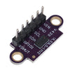
- VL53L0X Laser Ranging ToF Sensor
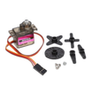
- MG90S Metal Gear Micro Servo
- 10K Slide Potentiometer Module — sets where the ball should sit
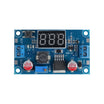
- LM2596 Adjustable Step-Down Module — 5 V for the servo
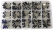
- Electrolytic Capacitor Kit — 470 µF across the servo supply
- 400-Point Breadboard
- Dupont Jumper Wires
External
- Corrugated card, foam board or thin plywood, and a hot glue gun
- A ping-pong ball, or any light, pale plastic ball 40–60 mm across
- An M3 bolt and nut for the pivot, and a stiff wire or straightened paperclip for the servo link
- A 9–12 V DC adapter for the LM2596
Note: the VL53L0X sees a cone about 25° wide, so a small ball far away fills less and less of its view. Keep the beam to about 35 cm, use a pale ball, and leave the far end of the beam open (or line it with something matte black) so the sensor's strongest echo always comes from the ball.
Step-by-Step Guide
Step 1 — Build the Frame


Goal: A light, stiff beam that pivots freely at one end.
What to do: Cut a base of about 40 × 20 cm, a tall support for the pivot end and a beam of about 34 cm. Glue two beam strips side by side with a slight V between them (or add low side walls) so the ball rolls straight instead of falling off. Push the M3 bolt through the support and the end of the beam as the pivot — it should rotate without wobble or friction. The other end of the beam stays free; the servo will lift and lower it.
Expected result: A beam that swings up and down smoothly about its pivot and is stiff along its length.
Step 2 — Add the Servo Link

Goal: Servo angle turned into beam tilt with no slop.
What to do: Glue the servo to a block on the base under the free end of the beam. Join the servo horn to the beam with a stiff link (a straightened paperclip bent into hooks works well) so that with the servo at 90° the beam sits roughly level. Any play in the link shows up later as a ball that wanders, so make the holes snug. You only need a few degrees of beam tilt either way — a long beam and a short horn give finer control.
Expected result: Turning the servo by hand moves the beam end smoothly up and down, with no free movement in between.
Step 3 — Mount the Sensor and Wire Everything

Goal: The sensor looking straight down the beam, and clean power for the servo.
What to do: Fix the VL53L0X at the pivot end, centred on the beam at ball height and looking along it. Mounted on the beam, it tilts with it, so it always looks straight down the track. Wiring to the Nano: VL53L0X VIN → 5V, GND → GND, SDA → A4, SCL → A5. Slide pot: VCC → 5V, GND → GND, output (OTA on most modules) → A0. Servo signal → D9. Set the LM2596 output to 5.0 V before connecting the servo, then LM2596 OUT+ → servo red, OUT− → servo brown and Nano GND, with a 470 µF capacitor across the servo supply.
Expected result: Three sensors and actuators on one Nano, the servo on its own supply, and every ground joined.
Step 4 — The Sketch
#include <Wire.h>
#include <VL53L0X.h>          // "VL53L0X" by Pololu
#include <Servo.h>

VL53L0X tof;
Servo beam;

const int SERVO_PIN = 9, POT_PIN = A0;
const int MIN_MM = 50, MAX_MM = 300;     // usable stretch of beam, measured from the sensor
const int TILT = 25;                     // max servo swing either side of level, degrees
int   LEVEL = 90;                        // servo angle that holds the beam level (Step 5)
int   DIR = 1;                           // -1 if the beam tilts the wrong way (Step 5)
float Kp = 0.12, Ki = 0.03, Kd = 0.07;   // starting gains, degrees per mm (Step 6)

float pos, vel, integral, setpoint = 175;
bool  tracking = false;
unsigned long lastUs;

void readCommands() {                    // type p0.15  i0.02  d0.08  l92  r-1  in the Serial Monitor
  static char buf[12];
  static byte n = 0;
  while (Serial.available()) {
    char c = Serial.read();
    if (c == '\n' || c == '\r') {
      if (n > 1) {
        buf[n] = 0;
        float v = atof(buf + 1);
        switch (buf[0]) {
          case 'p': Kp = v; break;
          case 'i': Ki = v; integral = 0; break;
          case 'd': Kd = v; break;
          case 'l': LEVEL = (int)v; break;
          case 'r': DIR = (v < 0) ? -1 : 1; break;
        }
        Serial.print(F("# Kp=")); Serial.print(Kp, 3);
        Serial.print(F(" Ki="));  Serial.print(Ki, 3);
        Serial.print(F(" Kd="));  Serial.print(Kd, 3);
        Serial.print(F(" level=")); Serial.print(LEVEL);
        Serial.print(F(" dir="));   Serial.println(DIR);
      }
      n = 0;
    } else if (n < sizeof(buf) - 1) {
      buf[n++] = c;
    }
  }
}

void setup() {
  Serial.begin(115200);
  Wire.begin();
  Wire.setClock(400000);
  beam.attach(SERVO_PIN);
  beam.write(LEVEL);
  tof.setTimeout(100);
  if (!tof.init()) {
    Serial.println(F("VL53L0X not found - check SDA A4 / SCL A5"));
    while (1) {}
  }
  tof.setMeasurementTimingBudget(20000);  // 20 ms per reading: fast enough for a rolling ball
  tof.startContinuous();
  lastUs = micros();
}

void loop() {
  readCommands();
  uint16_t mm = tof.readRangeContinuousMillimeters();   // waits for the next reading, ~45 per second
  unsigned long now = micros();
  float dt = (now - lastUs) / 1000000.0;
  lastUs = now;

  float target = map(analogRead(POT_PIN), 0, 1023, MIN_MM + 20, MAX_MM - 20);
  setpoint += 0.1 * (target - setpoint);                 // glide to a new target instead of jumping

  if (tof.timeoutOccurred() || mm > MAX_MM + 60) {      // lost the ball: past the far end or off the beam
    tracking = false;
    integral = 0;
    beam.write(LEVEL - DIR * TILT / 2);                  // tip gently toward the sensor to bring it back
    return;
  }
  if (!tracking) {                                       // ball just came into view: start clean
    pos = mm;
    vel = 0;
    tracking = true;
  }

  float prev = pos;
  pos += 0.5 * (mm - pos);                               // light smoothing of the range reading
  vel += 0.3 * ((pos - prev) / dt - vel);                // filtered ball speed in mm/s

  float err = setpoint - pos;                            // positive = ball too close to the sensor
  integral = constrain(integral + err * dt, -150, 150);  // limit wind-up
  float u = Kp * err + Ki * integral - Kd * vel;         // PID with derivative on measurement
  int tilt = constrain((int)u, -TILT, TILT);
  beam.write(LEVEL + DIR * tilt);

  Serial.print(F("pos:"));   Serial.print(pos, 0);       // Tools > Serial Plotter draws these
  Serial.print(F(",set:"));  Serial.print(setpoint, 0);
  Serial.print(F(",tilt:")); Serial.println(tilt);
}
What to do: Install VL53L0X by Pololu from the Library Manager, select "Arduino Nano" (try "ATmega328P (Old Bootloader)" if the upload times out) and upload. The derivative term uses the ball's measured speed rather than the change in error, so moving the slide pot never produces a sudden kick.
Expected result: The Serial Monitor (115200 baud) shows a steady stream of pos, set and tilt values, and pos follows the ball when you move it along the beam by hand.
Step 5 — Find Level and Direction
Goal: The controller knows what "level" is and which way is "away from the sensor".
What to do: In the Serial Monitor (line ending set to Newline) send p0, i0 and d0 — with all gains zero the servo simply holds the level angle. Place the ball mid-beam and send l88, l92 and so on until the ball barely drifts; note that number and put it in LEVEL in the sketch for next time. Now send p0.12 and place the ball near the sensor: the beam should tip so the ball rolls away from it, toward the target. If it tips the other way, send r-1 (and set DIR = -1 in the sketch).
Expected result: With only Kp active, the ball rolls toward the target and oscillates back and forth around it.
Step 6 — Tune the PID

Goal: A ball that settles quickly at the target and follows the slide pot.
What to do: Open Tools → Serial Plotter to watch pos against set. Start with i0 and set p so the ball swings steadily around the target without running off the end. Add damping with d: raise it in small steps until each swing is smaller than the last and the ball stops within one or two. If the beam starts buzzing or twitching, Kd is too high for the sensor noise — back off a little. Finally add a small i (0.01–0.05) to remove any steady offset between the ball and the target. Every rig is different — horn length, beam length and ball weight all change the numbers — so treat the starting gains as just that. Once it's tuned, write your values into the sketch.
Expected result: Move the slide pot and the ball rolls to the new spot and stops; nudge it with a finger and it comes straight back.
Step 7 — Take It Further
Goal: Better control and new experiments.
What to do: Mount an MPU6050 on the beam and run a fast inner loop on beam angle with this ball loop on top — cascaded control is how real balancing systems are built. Add an OLED to show the gains and position without a computer. Record step responses from the plotter and compare them with what the textbook model predicts. Or go two-dimensional: a flat plate on two servos with a camera or touch panel to sense the ball is the next classic, the ball-and-plate.
Expected result: A desk-sized control lab you can keep learning on.
Conclusion
With an Arduino Nano, a VL53L0X time-of-flight sensor, one MG90S servo and a slide potentiometer, you built the classic ball-and-beam and closed the loop with a PID controller you can tune while it runs. The ideas here — measure, compare with a setpoint, correct proportionally, damp with speed, trim with the integral — are the same ones that hold drones level and keep 3D printer hotends on temperature.
Want the exact parts used in this build? Grab them from ShillehTek.com. If you want help customizing this project, check out our IoT consulting services.
Credits
All photos and images in this tutorial are credited to Karem BenChikha on Hackster.io. The original guide by Karem BenChikha served as the reference for this ShillehTek version. We thank them for their excellent work in the maker community.





.png?v=25000753014097803521791168436)

.png?v=68677308723310773341791168436)