

Project Overview
Arduino Nano + EM4100 125 kHz RFID reader: In this build, you will read EM4100 card IDs, store authorized cards in EEPROM, and unlock an electric strike using a relay for a simple multi-card RFID door lock.

Two flavors of RFID dominate maker projects: 13.56 MHz (the RC522, MIFARE) and 125 kHz (the EM4100, HT4168). The 125 kHz family is what many commercial proximity-card door locks use. The EM4100 standard is open and easy to read with an Arduino and a low-cost 125 kHz reader module. For under $15 of parts, you can build an RFID door lock with multi-card support and Wiegand-style access logging.
This guide walks through the wiring, reads cards, stores authorized IDs in EEPROM, drives an electric strike lock through a relay, and covers upgrade ideas like time-of-day rules, master/admin cards, and WiFi-logged entry events.
- Time: 45 to 90 minutes
- Skill level: Intermediate
- What you will build: An Arduino Nano-based RFID access controller that unlocks a strike for authorized EM4100 card IDs stored in EEPROM.
Parts List
From ShillehTek
- Arduino Nano V3.0 - reads the RFID module, checks EEPROM, and drives the relay.
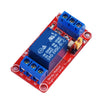
- 1-Channel 12V Relay Module - switches power to the electric strike.
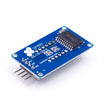
- TM1637 4-Bit Display - optional, for showing card ID.
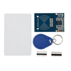
- RC522 RFID Reader (13.56 MHz) - optional alternative if you want to use MIFARE cards instead.
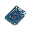
- ESP8266 D1 Mini - optional upgrade for WiFi logging.
External
- 125 kHz RFID reader module (RDM6300 or similar) - outputs UART serial when a card is read.
- EM4100 RFID cards or HT4168 keytag fobs.
- 12 V electric strike lock or solenoid.
- 12 V DC power supply rated for the lock.
- Jumper wires, breadboard or perfboard, and basic tools.
Note: The RDM6300 typically uses 5V TTL serial. The relay module in this guide is treated as active-low (IN goes LOW to energize). The lock power (12V) must remain isolated from the Arduino 5V side except through the relay contacts.
Step-by-Step Guide
Step 1 - Choose 125 kHz vs 13.56 MHz for your use case
Goal: Pick the RFID type that matches your cards and security needs.
What to do: If you only need a yes/no check against a list of authorized cards, 125 kHz EM4100 is the simplest and cheapest approach. If you need read/write card storage or more advanced credentials, consider 13.56 MHz MIFARE options instead.

- 125 kHz EM4100: read-only ID (40 bits / 10 hex chars), passive cards last decades, about 3 to 5 cm read range. Best for "is this a known card?" access control.
- 13.56 MHz MIFARE: read/write, often around 1 KB user data on the card, about 3 to 5 cm range. Use when you want to store extra info on the card (balance, access level).
Expected result: You know whether you are building for EM4100 125 kHz IDs (this guide) or a 13.56 MHz MIFARE workflow.
Step 2 - Wire the reader and the relay
Goal: Connect the RDM6300 (or similar) to the Arduino Nano, and wire the relay to switch the 12V lock.
What to do: Use the wiring map below. The reader TX goes to the Arduino software-serial RX pin. The relay IN pin is driven by the Arduino and the lock power is routed through COM and NO on the relay.
Wiring map:
RDM6300 / 125kHz Reader     Arduino Nano
VCC                      -> 5V
GND                      -> GND
TX                       -> D2  (RX in SoftwareSerial)
ANT1, ANT2               -> the included coil antenna (already wired)

Relay Module                Arduino Nano
VCC                      -> 5V
GND                      -> GND
IN                       -> D7 (active LOW)
Lock(+)                  -> Relay NO
Lock(-)                  -> 12V GND
+12V                     -> Relay COM
Expected result: The Arduino can receive card data from the reader, and it can energize the relay to apply 12V to the strike lock.
Step 3 - Understand the card data format and test a read
Goal: Verify you can read a 10-character EM4100 ID from the serial stream.
What to do: The RDM6300 streams a 14-byte serial frame whenever a card is in range. Use the format below and upload the test sketch to print the ID to the Serial Monitor.
Frame format:
0x02 [10 hex chars of card ID] [2 hex chars of checksum] 0x03Code:
#include <SoftwareSerial.h>
SoftwareSerial rfid(2, 3);  // RX, TX

void setup() {
  Serial.begin(9600);
  rfid.begin(9600);
}

void loop() {
  if (rfid.available() >= 14) {
    if (rfid.read() == 0x02) {
      char id[11] = {0};
      for (int i = 0; i < 10; i++) id[i] = rfid.read();
      Serial.print("ID: "); Serial.println(id);
      while (rfid.available()) rfid.read();   // flush
    }
  }
}
Expected result: When you wave a card, the 10-character ID prints to Serial. Write it down because it is the card’s permanent identity.
Step 4 - Store and check authorized cards in EEPROM
Goal: Create a simple authorization check that compares a scanned ID to IDs stored in EEPROM.
What to do: This example stores up to 10 cards (100 bytes total, 10 bytes per ID) in the Nano’s EEPROM. The enrollment flow described here is:
- Power on with the ENROLL button held.
- Wave a card and write its ID to the next free EEPROM slot.
- Release the button; the card is now authorized.

Code:
#include <EEPROM.h>
const int MAX_CARDS = 10;

bool isAuthorized(const char* id) {
  for (int i = 0; i < MAX_CARDS; i++) {
    char stored[11] = {0};
    for (int j = 0; j < 10; j++)
      stored[j] = EEPROM.read(i * 10 + j);
    if (strncmp(stored, id, 10) == 0) return true;
  }
  return false;
}
Expected result: You can call isAuthorized(id) and get a true/false result based on what is stored in EEPROM.
Step 5 - Drive the lock relay based on authorization
Goal: Unlock for authorized cards and deny access for unknown cards.
What to do: Use the loop below to read an ID, check authorization, then unlock by pulling the relay pin LOW for a fixed time. Flash an OK LED for success and a FAIL LED for denial.
Code:
const int LOCK_RELAY = 7;
const int OK_LED     = 8;
const int FAIL_LED   = 9;
const unsigned long UNLOCK_MS = 5000;

void loop() {
  if (rfid.available() >= 14 && rfid.read() == 0x02) {
    char id[11] = {0};
    for (int i = 0; i < 10; i++) id[i] = rfid.read();
    while (rfid.available()) rfid.read();
    if (isAuthorized(id)) {
      digitalWrite(LOCK_RELAY, LOW);    // unlock
      digitalWrite(OK_LED, HIGH);
      delay(UNLOCK_MS);
      digitalWrite(LOCK_RELAY, HIGH);   // re-lock
      digitalWrite(OK_LED, LOW);
    } else {
      digitalWrite(FAIL_LED, HIGH);
      delay(1000);
      digitalWrite(FAIL_LED, LOW);
    }
  }
}
Expected result: Authorized cards unlock the door for the configured time; unauthorized cards trigger the failure indicator.
Step 6 - Consider upgrade paths for a more product-like system
Goal: Understand common feature upgrades you can add after the basic lock works.
What to do: If you want to expand the project beyond a basic allow-list door lock, these are common additions:

- Master card: reserve EEPROM slot 0 as the master so only it can enroll/delete cards.
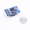
- Time-of-day rules: add a DS3231 RTC and reject some cards outside allowed hours.
- WiFi event log: swap the Nano for an ESP8266 D1 Mini and POST reads to a Google Sheet or Home Assistant.
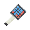
- Backup keypad: add a 4x4 keypad for a PIN fallback.
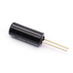
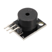
- Anti-tamper: add a tilt switch that triggers a buzzer if the unit is moved.
- Time-limited admin cards: create visitor cards that auto-expire.
Expected result: You have a clear roadmap for turning the basic RFID door lock into a more complete access system.
Step 7 - Understand the security limitations of EM4100
Goal: Make an informed decision about when EM4100 is appropriate.
What to do: EM4100 is not a secure protocol. The card ID is broadcast in plaintext and can be cloned with low-cost tools. For workshops, garages, maker spaces, or low-risk doors, it can be acceptable. For higher security needs, use 13.56 MHz credentials designed for encrypted challenge-response (for example, MIFARE DESFire EV2/EV3 or HID iCLASS).
Expected result: You understand the tradeoff between cost and security for 125 kHz EM4100 systems.
Conclusion
Using a 125 kHz EM4100 reader with an Arduino Nano and a relay is one of the cheapest ways to build a working RFID door lock with EEPROM-based multi-card access. Once the basic read-check-unlock loop works, you can expand it with admin controls, time rules, and WiFi logging.
Want the exact parts used in this build? Grab them from ShillehTek.com. If you want help customizing this project or building something for your product, check out our IoT consulting services.
Attribution: This guide was inspired by "Open Sesame! Arduino RFID Lock and Automations" on Instructables.



.png?v=25000753014097803521791168436)

.png?v=68677308723310773341791168436)


