

Project Overview
Arduino Nano + MP3-TF-16P (DFPlayer Mini) + SH1106 OLED: Build a standalone MP3 player that plays tracks from a microSD card, shows a simple menu UI on a 1.3 inch OLED, and lets you control playback, volume, and EQ with buttons (with settings saved to EEPROM).
- Time: 1 to 2 hours
- Skill level: Intermediate
- What you will build: A pocket-style MP3 player with a 1.3 inch OLED menu, three-button controls, and settings that persist after power-off using EEPROM.

Parts List
From ShillehTek
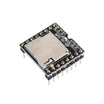
- MP3-TF-16P Mini MP3 Player Module with TF Card Slot - DFPlayer Mini compatible audio playback module
- Arduino Nano V3.0 Pre-Soldered CH340G - microcontroller for UI, buttons, and serial control
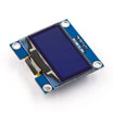
- 1.3 inch I2C OLED Display (SH1106) - menu and status display
- Tactile Push Buttons - three buttons for prev/select/next
- Resistor Kit - 1x 1 kΩ (DFPlayer RX protection), 3x 100 Ω (RGB LED)
- 830-Point Breadboard - quick prototyping
- Dupont Jumper Wires - breadboard wiring
External
- Small 8 Ω speaker (3 W or less, driven directly by the module)
- MicroSD card (FAT32) loaded with MP3 files
- RGB LED (common cathode)
Note: The MP3-TF-16P RX pin is 3.3 V logic. Feed it through a 1 kΩ series resistor from the Arduino Nano TX line.
Step-by-Step Guide
Step 1 - Understand the Architecture
Goal: Know what each part does before wiring.
What to do: The MP3-TF-16P is a complete audio system: it reads MP3s from its TF card slot, decodes them, and drives a small speaker directly from its SPK pins.
The Arduino Nano does not process audio. It sends serial commands (play, next, volume up) over SoftwareSerial at 9600 baud. This lets the Nano handle the OLED menu, read button presses, and drive the RGB LED.
Expected result: A clear mental model: Nano = UI and control, MP3-TF-16P = the actual player.
Step 2 - Prepare the MicroSD Card
Goal: Format and name files so the module can reliably find tracks.
What to do: Format the microSD card as FAT32. Create a folder named 01 and copy your tracks as 001.mp3, 002.mp3, and so on.
This numbered scheme is what lets the firmware jump to specific tracks using playFolder().
Expected result: A card the DFPlayer firmware can index quickly.
Step 3 - Wire Everything
Goal: Assemble the full circuit on a breadboard.
What to do: Wire the MP3-TF-16P VCC to 5V and GND to GND. Connect module TX to Nano D12. Connect module RX to Nano D13 through a 1 kΩ series resistor. Connect the speaker across SPK1 and SPK2.
Connect the SH1106 OLED on I2C: SDA to A4 and SCL to A5.
Buttons: previous on D2, select on D5, next on D3. Wire each button to GND and use internal pull-ups (D2 and D3 are interrupt pins, which helps track skipping respond quickly).
RGB LED: run each color leg through a 100 Ω resistor to D11, D10, and D6 (common cathode to GND).

Expected result: Hardware complete and powered over USB.
Step 4 - Install the Libraries
Goal: Install the libraries needed for playback control and the OLED UI.
What to do: In the Arduino IDE Library Manager, install DFRobotDFPlayerMini (playback commands) and U8g2 (OLED graphics). SoftwareSerial and EEPROM are included with the Arduino IDE.
For this 1.3 inch OLED module, use the SH1106 hardware I2C constructor.
Code:
#include <SoftwareSerial.h>
#include <DFRobotDFPlayerMini.h>
#include <U8g2lib.h>
#include <Wire.h>
#include <EEPROM.h>

#define BTN_PREV   2    // interrupt pin
#define BTN_NEXT   3    // interrupt pin
#define BTN_SELECT 5
#define LED_R 11
#define LED_G 10
#define LED_B 6

SoftwareSerial mp3Serial(12, 13);   // RX, TX
DFRobotDFPlayerMini player;
U8G2_SH1106_128X64_NONAME_F_HW_I2C u8g2(U8G2_R0, U8X8_PIN_NONE);

void setup() {
  u8g2.begin();
  pinMode(BTN_PREV, INPUT_PULLUP);
  pinMode(BTN_NEXT, INPUT_PULLUP);
  pinMode(BTN_SELECT, INPUT_PULLUP);
  pinMode(LED_R, OUTPUT); pinMode(LED_G, OUTPUT); pinMode(LED_B, OUTPUT);

  mp3Serial.begin(9600);
  player.begin(mp3Serial);

  player.volume(EEPROM.read(0));        // restore saved volume (0-30)
  player.EQ(EEPROM.read(1));            // restore saved EQ preset
  player.playFolder(1, EEPROM.read(2)); // resume the last track
}
Expected result: Your sketch compiles once the libraries are installed.
Step 5 - Flash the Full Player Firmware
Goal: Upload the complete multi-file sketch to the Arduino Nano.
What to do: Grab the complete project from the original author's GitHub repository. It is organized into multiple tabs (AudioPlayer, Input, and display) plus the main sketch.
Open the main .ino in the Arduino IDE (the other tabs load automatically when they are in the same folder) and upload to the Nano.
Expected result: Upload succeeds and the OLED boots into the player UI.
Step 6 - Play
Goal: Use the buttons and UI to control playback.
What to do: Tap next/previous to change tracks. Use the select button to enter the side menu for play/pause, volume (0-30), and equalizer presets. The RGB LED provides feedback as you adjust settings.
Because settings are written to EEPROM, the player restores the same volume, EQ, and track after power-off.
Expected result: Music plays from the microSD card, the OLED menu works, and settings persist across reboots.
Conclusion
Using an Arduino Nano, an MP3-TF-16P (DFPlayer Mini) module, and an SH1106 OLED, you built a standalone MP3 player with real buttons, a menu UI, and saved settings via EEPROM. This project is a practical way to learn serial-controlled modules, I2C displays, and input handling on the Nano.
Want the exact parts used in this build? Grab them from ShillehTek.com. If you want help customizing this project or building something for your product, check out our IoT consulting services.
Credits
All photos and images in this tutorial are credited to DKARDU on Hackster.io. The original guide by DKARDU served as the reference for this ShillehTek version. We thank them for their excellent work in the maker community.






.png?v=25000753014097803521791168436)

.png?v=68677308723310773341791168436)


