

Project Overview
ESP32 + GC9A01 Round Display VU Meter: Build a stereo retro analog-style VU meter using two 1.28 in GC9A01 round TFT displays, each driven by its own ESP32, with peak-indicator LEDs that react to your audio signal.
- Time: ~3 hours
- Skill level: Beginner
- What you will build: A stereo desktop VU meter with animated retro dials, damped needle motion, and LED peak warnings, fed by a simple diode-capacitor envelope follower.

Parts List
From ShillehTek
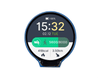
- 2x 1.28" Round IPS LCD Display (GC9A01, 240x240) - one display per stereo channel
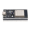
- 2x ESP32 Dev Board (CP2102, USB-C, 38-Pin) - one ESP32 per display/channel
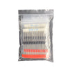
- Common Diode Kit - 2x 1N4148 small-signal diodes for the envelope followers
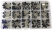
- Electrolytic Capacitor Kit - 2 capacitors for the envelope followers
- Resistor Kit - bleed resistors and LED current-limiting resistors
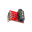
- 3.5mm Stereo Audio Jack Breakout - clean way to tap left and right audio
- 830-Point Breadboard - prototyping the circuits
- Dupont Jumper Wires - wiring the SPI and analog connections
External
- 2x LEDs (peak indicators)
- A small enclosure or 3D-printed case for the finished meter
- An audio source (line-out or headphone signal)
Note: One ESP32 per channel keeps the needle animation smooth on both dials. The GC9A01 uses 3.3 V logic, which matches the ESP32, so no level shifting is needed.
Step-by-Step Guide
Step 1 - Understand the Retro VU Meter Concept
Goal: Understand the design you are recreating.
What to do: A traditional VU meter uses a sensitive galvanometer where the needle deflects with the strength of the audio signal across a calibrated scale. The GC9A01 round 240x240 screen is a great canvas to redraw that instrument in software with retro colors. This build adapts dial-and-gauge rendering work from the thesolaruniverse project to display real signal levels instead of demo values.

Expected result: You have a clear target: two retro dials that move with left and right audio.
Step 2 - Gather One ESP32 and One Display per Channel
Goal: Prepare two identical channel builds.
What to do: Build each channel as its own unit: one ESP32 drives one GC9A01 display over SPI. Because both are 3.3 V logic, the wiring is straightforward.

Expected result: Two matched sets of parts ready for wiring.
Step 3 - Wire the SPI Display and Envelope Follower Circuit
Goal: Connect the GC9A01 over SPI and convert audio into a DC level for the ESP32 ADC.
What to do: Wire each GC9A01 to its ESP32 as follows: CS to GPIO15, DC to GPIO2, SCK to GPIO18, SDA/MOSI to GPIO23, VCC to 3.3V, and GND to GND.
For each audio channel, build a simple envelope follower: place a small-signal diode in series with the audio line, connect a capacitor from the diode output to ground, and add a bleed resistor so the level falls between peaks. Feed the resulting DC level into an ESP32 ADC input. Add a peak LED with a current-limiting resistor for each channel.

Expected result: Both channels are wired identically, and audio is tapped from the stereo jack breakout.
Step 4 - Flash the Firmware
Goal: Load the left- and right-channel sketches.
What to do: Install Adafruit GFX and Adafruit GC9A01A from the Arduino Library Manager. Use the full left and right sketches from the original project page. The core drawing loop looks like this:
Code:
#include "SPI.h"
#include "Adafruit_GFX.h"
#include "Adafruit_GC9A01A.h"

#define TFT_DC 2
#define TFT_CS 15
#define DEG2RAD 0.0174532925

Adafruit_GC9A01A tft(TFT_CS, TFT_DC);

const int AUDIO_IN = 34;   // envelope follower output
float needle = 0;          // current needle angle

void setup() {
  tft.begin();
  tft.fillScreen(0xAB21);  // retro dial background color
  // draw the scale arc, tick marks and labels once here
}

void loop() {
  int raw = analogRead(AUDIO_IN);
  float target = map(raw, 0, 4095, -45, 45);   // level  needle angle
  needle += (target - needle) * 0.25;          // damped, homogeneous motion

  // erase the previous needle, then redraw at the new angle
  float x = 120 + 80 * sin(needle * DEG2RAD);
  float y = 150 - 80 * cos(needle * DEG2RAD);
  tft.drawLine(120, 150, x, y, GC9A01A_RED);

  delay(20);
}
Expected result: Each display boots into a retro dial with a resting needle.
Step 5 - Assemble Both Channels Into One Enclosure
Goal: Package the project as a single stereo unit.
What to do: Mount the two displays side by side on the front panel. Place the ESP32 boards and envelope follower circuits behind them, and bring the stereo input out to the 3.5 mm jack. Keep analog wiring short to reduce noise pickup.

Expected result: A tidy, self-contained stereo VU meter.
Step 6 - Feed Audio and Observe the Needles and Peak LEDs
Goal: Verify the meter responds to music.
What to do: Feed a line-level signal into the stereo input and watch both needles track the music with a smooth, analog-like lag. When a channel exceeds the safe level, its peak LED lights.

Expected result: A working stereo VU meter with animated dials and peak indication.
Conclusion
This project uses two ESP32 boards and two GC9A01 round TFT displays to recreate a stereo analog-style VU meter with damped needle motion and peak LEDs. With a simple diode-capacitor envelope follower feeding the ESP32 ADC, the needles move in sync with real audio.
Want the exact parts used in this build? Grab them from ShillehTek.com. If you want help customizing this project or building something for your product, check out our IoT consulting services.
Photo and original guide reference: Mirko Pavleski (mircemk) on Hackster.io.





.png?v=25000753014097803521791168436)

.png?v=68677308723310773341791168436)


