

Project Overview
Gesture-Controlled LCD Menu with APDS-9960: Build an Arduino Nano + APDS-9960 gesture sensor interface that drives a 16x2 I2C LCD menu. Swipe up/down to navigate options and swipe left/right to switch loads (LEDs in this demo) off and on, with both the sensor and display sharing the same I2C bus.
- Time: 1 to 2 hours
- Skill level: Beginner to Intermediate
- What you will build: A button-free LCD menu that you navigate and activate entirely with hand gestures.

Parts List
From ShillehTek
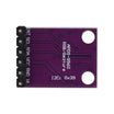
- APDS-9960 RGB Gesture, Proximity & Color Sensor Module - reads swipe direction over I2C.
- Arduino Nano V3 (ATmega328P) - runs the menu logic and controls outputs.
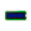
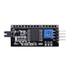
- LCD1602 16x2 Display Module with an PCF8574 I2C backpack - displays the menu via I2C.
- 400-Point Solderless Breadboard - quick prototyping.
- 120pcs 20cm Dupont Jumper Wires - wiring between modules.
- Metal Film Resistor Kit - series resistors for the LEDs.
External
- Two 5mm LEDs (the loads you switch with gestures)
Note: The APDS-9960 is a 3.3V sensor. Power it from the Nano's 3V3 pin, not 5V. The I2C lines can share the bus with the 5V LCD backpack.
Step-by-Step Guide
Step 1 - Why gestures instead of buttons
Goal: Understand the design win before wiring anything.
What to do: Consider what a four-button menu costs you: four input pins, four debounce routines, and four parts that wear out. The APDS-9960 replaces all of it with a single I2C device (two data wires) that reports four distinct swipe directions (up, down, left, right), plus proximity and color sensing you can use in later projects.
The menu logic becomes one gesture read per loop.

Expected result: A clear picture of the architecture: one sensor in, one LCD out, two LEDs as switchable loads.
Step 2 - Meet the APDS-9960
Goal: Know how the sensor detects swipes.
What to do: The APDS-9960 pairs an IR LED with four directional photodiodes. When your hand passes over it, the order in which reflected light hits the photodiodes tells the chip which direction you swiped.
In this project it runs in proximity-triggered gesture mode: bring a finger near the module and it wakes gesture detection automatically.

Expected result: You know the sensor needs 3.3V power and an I2C connection.
Step 3 - Wire the circuit
Goal: Put the sensor and display on the same I2C bus and hook up the LED loads.
What to do: Make these connections on the breadboard:
APDS-9960 VCC  ->  Nano 3V3
APDS-9960 GND  ->  Nano GND
APDS-9960 SDA  ->  Nano A4
APDS-9960 SCL  ->  Nano A5

LCD I2C backpack VCC -> Nano 5V, GND -> GND
LCD I2C backpack SDA -> A4, SCL -> A5 (shared bus, address 0x27)

LED1 (+ resistor) -> D2    LED2 (+ resistor) -> D3
Expected result: Both I2C devices share A4/A5, and the two LEDs sit on D2 and D3 through series resistors.
Step 4 - Upload the full sketch
Goal: Get the complete gesture-menu firmware running.
What to do: Install the Adafruit APDS9960 and LiquidCrystal_I2C libraries, then upload the sketch below.
#include "SoftwareSerial.h"
#include <LiquidCrystal_I2C.h>
#include "Adafruit_APDS9960.h"

Adafruit_APDS9960 apds;
LiquidCrystal_I2C lcd(0x27,16,2);
SoftwareSerial mySoftwareSerial(10, 11); // RX, TX

byte count = 2;

void setup()
{
  Serial.begin(9600);
  Wire.begin();

  lcd.init();
  lcd.backlight();

  for(byte i = 2; i <= 4; i++)
  {
    pinMode(i, OUTPUT);
  }

  if(!apds.begin())
  {
    Serial.println("Failed to initialize the sensor. Check your connections!");
  }
  else
    Serial.println("Device initialized!");

  apds.enableProximity(true);
  apds.enableGesture(true);

  show_menu(count);
}

void loop()
{
  uint8_t gesture = apds.readGesture();

  if(gesture == APDS9960_UP)
  {
    count++;
    if(count > 4) { count = 4; }
    show_menu(count);
  }

  if(gesture == APDS9960_LEFT)
  {
    if(count == 2) { digitalWrite(2, LOW); }
    if(count == 3) { digitalWrite(3, LOW); }
    if(count == 4) { digitalWrite(2, LOW); digitalWrite(3, LOW); }
  }

  if(gesture == APDS9960_RIGHT)
  {
    if(count == 2) { digitalWrite(2, HIGH); }
    if(count == 3) { digitalWrite(3, HIGH); }
    if(count == 4) { digitalWrite(2, HIGH); digitalWrite(3, HIGH); }
  }

  if(gesture == APDS9960_DOWN)
  {
    count--;
    if(count < 2) { count = 2; }
    show_menu(count);
  }
}

void show_menu(byte option)
{
  if(option == 2)
  {
    lcd.clear();
    lcd.setCursor(0,0);
    lcd.print("-> LED1");
    lcd.setCursor(0,1);
    lcd.print("   LED2");
    return;
  }

  if(option == 3)
  {
    lcd.clear();
    lcd.setCursor(0,0);
    lcd.print("   LED1");
    lcd.setCursor(0,1);
    lcd.print("-> LED2");
    return;
  }

  if(option == 4)
  {
    lcd.clear();
    lcd.setCursor(0,0);
    lcd.print("-> LED1 and LED2");
    return;
  }

  return;
}
Expected result: The sketch compiles, and the serial monitor prints "Device initialized!" on boot.
Step 5 - How setup prepares the system
Goal: Understand the initialization so you can adapt it.
What to do: In setup() the sketch starts serial and I2C, initializes the LCD with its backlight, and configures pins 2 to 4 as outputs in a loop.
It then tests the sensor with apds.begin(). The key lines are apds.enableProximity(true) and apds.enableGesture(true): proximity mode arms the sensor so gesture detection engages when your finger approaches. Finally it draws the first menu screen.

Expected result: The menu appears on the LCD immediately after power-up.
Step 6 - How the loop reads gestures
Goal: See how four swipes map to navigation and switching.
What to do: Each pass of loop() calls apds.readGesture() and compares the result against APDS9960_UP, DOWN, LEFT, and RIGHT.
Up and down swipes increment or decrement the count variable (clamped between 2 and 4) and redraw the menu. A right swipe drives the selected load pin HIGH (on) and a left swipe drives it LOW (off). Option 4 controls both LEDs at once. The count values deliberately match the Arduino pin numbers.

Expected result: Swiping over the sensor moves the menu cursor, and left/right swipes toggle the LEDs.
Step 7 - Optional: Move it to a dedicated PCB
Goal: Make the project permanent and reusable.
What to do: The original author designed a small carrier PCB in EasyEDA that hosts the Nano, the 16x2 LCD header, and the gesture sensor, with screw terminals broken out for every Nano pin so you can attach real loads instead of demo LEDs.
If you like the project, laying out a similar board (or wiring it on a prototype PCB) turns the breadboard demo into a reusable gesture control panel.


Expected result: A permanent gesture-control interface you can drop into future builds.
Conclusion
You built a fully gesture-driven menu system: an APDS-9960 reading four swipe directions, an Arduino Nano running the menu logic, and a 16x2 I2C LCD showing the options with no mechanical buttons.
This same pattern (read gesture, update state, redraw the screen, drive outputs) can scale to relay boards and other touchless control interfaces.
Want the exact parts used in this build? Grab them from ShillehTek.com. If you want help customizing this project or building something for your product, check out our IoT consulting services.






.png?v=25000753014097803521791168436)

.png?v=68677308723310773341791168436)


