

Project Overview
HC-12 Long-Range Wireless Telemetry: Build a two-node radio link where an Arduino Nano reads a DHT11 sensor and transmits temperature and humidity to an Arduino Uno base station with an LCD, and the base can send commands back to toggle LEDs on the remote node. No WiFi, no pairing, up to about 1 km line-of-sight.
- Time: 2 to 3 hours
- Skill level: Intermediate
- What you will build: A bidirectional 433 MHz telemetry system: remote sensor node (Nano + DHT11 + HC-12) and base station (Uno + 16x2 I2C LCD + buttons + HC-12).

Parts List
From ShillehTek
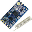
- 2x HC-12 433MHz Long-Range Wireless Serial Transceiver (SI4438) - one for the sensor node and one for the base station
- Arduino Uno R3 - base station controller
- Arduino Nano V3.0 Pre-Soldered - remote sensor node controller
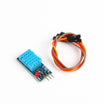
- DHT11 Temperature & Humidity Sensor - environmental readings for the remote node
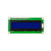
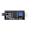
- LCD1602 16x2 Display + PCF8574 I2C Backpack - shows temperature and humidity on the base station
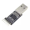
- CP2102 USB to TTL Serial Converter - used to send AT commands during HC-12 configuration
- Tactile Push Buttons - 2 buttons for sending command bytes from the base station
- Resistor Kit - 2x 10 kΩ for buttons, plus LED resistors
- 2x 830-Point Breadboard - one per node for prototyping
- Dupont Jumper Wires - breadboard wiring
External
- 1x red LED and 1x blue LED - for the remote-control demo
- External 5V supply for configuring the HC-12 - some USB-serial adapters cannot source enough current
- Optional: custom PCBs if you want a permanent build
Note: Both HC-12 modules must be configured with the same baud rate, channel, and FU mode or they will not hear each other.
Step-by-Step Guide
Step 1 - Meet the HC-12
Goal: Understand what makes this module special before configuring it.
What to do: The HC-12 is a UART radio transceiver operating from 433.4 to 473.0 MHz across 100 selectable channels. Whatever bytes you push into its RX/TX pins come out the other module's serial port, so it behaves like an invisible serial cable. It ships with a coil (helical) antenna and also has a U.FL connector if you want to attach an external antenna for more range. Wired systems fall apart when the sensor sits far from the display, and this link is the fix: readings from a shed, garage, greenhouse, or attic arrive with no cabling at all.
Expected result: You know both modules must share the same settings, and that ranges up to about 1 km are possible in FU3 mode with clear line of sight.
Step 2 - Wire the HC-12 for AT Configuration
Goal: Put the module into command mode so you can change its settings.
What to do: Connect the HC-12 to a USB-serial converter: TXD to RX, RXD to TX, and critically, pull the SET pin to GND. That is what drops the module into configuration mode. Power the module from a solid external 5V rail and tie all grounds together; many USB-serial adapters cannot source enough current for the radio on their own.

These are the AT commands you'll be using:


Expected result: Module wired, powered, and sitting in command mode.
Step 3 - Configure Both Modules with Termite
Goal: Set baud, channel, power, and mode identically on both radios.
What to do: Install the free Termite serial terminal, open Settings, select your adapter's COM port, 9600 baud, and append CR+LF. Type AT; the module should answer OK. Then send the configuration, one command at a time. This build uses: 9600 bps (AT+B9600), channel 5 (AT+C005), 11 dBm transmit power (AT+P5), and mode FU3 (AT+FU3). Repeat the exact same sequence on the second module.


Expected result: Both radios answer OK and carry identical settings.
Step 4 - Build the Base Station (Uno)
Goal: Assemble the receiver/controller node.
What to do: On the Uno: HC-12 TXD to D7, RXD to D8 (SoftwareSerial), the I2C LCD backpack on A4 (SDA) and A5 (SCL) with VCC and GND, and two tactile buttons on D2 (B0) and D3 (B1) wired active-low with 10 kΩ resistors. The I2C backpack is the wiring saver here; the whole display needs just four wires.

Expected result: Base hardware complete.
Step 5 - Build the Sensor Node (Nano)
Goal: Assemble the remote transmitter.
What to do: On the Nano: HC-12 TXD to D7, RXD to D8, the DHT11 data pin to a digital pin (match the diagram), and the red LED on D4 and blue LED on D3 through current-limiting resistors.

Expected result: Sensor hardware complete.
Step 6 - Program the Base Station
Goal: Receive packed sensor bytes, display them, and send LED commands.
What to do: The protocol is simple: the sensor sends 4 bytes every 3 seconds; temperature x100 split into high/low bytes, then humidity x100 the same way. The base rebuilds each value as (hi*256 + lo)/100 and sanity-checks it before display. Button presses transmit a single command byte (1 = red, 2 = blue).
Code:
#include <SoftwareSerial.h>
#include <Wire.h>
#include <LiquidCrystal_I2C.h>

#define B0 2
#define B1 3

SoftwareSerial HC12(7, 8);        // RX (to HC-12 TXD), TX (to HC-12 RXD)
LiquidCrystal_I2C lcd(0x27, 16, 2);

byte RX[4];

void setup() {
  pinMode(B0, INPUT_PULLUP);
  pinMode(B1, INPUT_PULLUP);
  HC12.begin(9600);
  lcd.init();
  lcd.backlight();
  lcd.print("Waiting data...");
}

void loop() {
  if (!digitalRead(B0)) { HC12.write((byte)1); delay(250); }  // toggle red
  if (!digitalRead(B1)) { HC12.write((byte)2); delay(250); }  // toggle blue

  if (HC12.available() >= 4) {
    for (byte i = 0; i < 4; i++) RX[i] = HC12.read();
    float temp = (RX[0] * 256 + RX[1]) / 100.0;
    float humi = (RX[2] * 256 + RX[3]) / 100.0;

    if (temp >= 0 && temp <= 100 && humi >= 0) {
      lcd.setCursor(0, 0);
      lcd.print("Temp: "); lcd.print(temp, 1); lcd.print((char)223); lcd.print("C  ");
      lcd.setCursor(0, 1);
      lcd.print("Hum:  "); lcd.print(humi, 1); lcd.print("%   ");
    }
  }
}
Expected result: Sketch compiles and uploads to the Uno.
Step 7 - Program the Sensor Node
Goal: Read the DHT11 on a timer and obey LED commands.
What to do: Note the non-blocking millis() timer; the node keeps listening for commands while it waits out the 3-second reporting interval.
Code:
#include <SoftwareSerial.h>
#include <DHT.h>

#define RED_LED  4
#define BLUE_LED 3
#define DHTPIN   5          // match the data pin in your wiring
#define DHTTYPE  DHT11

SoftwareSerial HC12(7, 8);  // RX, TX
DHT dht(DHTPIN, DHTTYPE);

byte TX[4];
unsigned long lastSend = 0;

void setup() {
  pinMode(RED_LED, OUTPUT);
  pinMode(BLUE_LED, OUTPUT);
  HC12.begin(9600);
  dht.begin();
}

void loop() {
  while (HC12.available() > 0) {
    byte command = HC12.read();
    switch (command) {
      case 1: digitalWrite(RED_LED,  !digitalRead(RED_LED));  break;
      case 2: digitalWrite(BLUE_LED, !digitalRead(BLUE_LED)); break;
    }
  }

  if (millis() - lastSend >= 3000) {
    lastSend = millis();
    float temp = dht.readTemperature();
    float humi = dht.readHumidity();

    if (!isnan(temp) && !isnan(humi)) {
      int t = temp * 100;
      int h = humi * 100;
      TX[0] = highByte(t);  TX[1] = lowByte(t);
      TX[2] = highByte(h);  TX[3] = lowByte(h);
      for (byte i = 0; i < 4; i++) HC12.write(TX[i]);
    }
  }
}
Expected result: Sketch compiles and uploads to the Nano.
Step 8 - Test the Link
Goal: Watch live telemetry flow and commands go the other way.
What to do: Power both nodes. Within a few seconds the base LCD should show temperature and humidity, refreshing every 3 seconds. Press B0; the red LED on the remote node toggles. Press B1 for the blue one. Then start walking: move the sensor node farther away and see how far the link holds.


Expected result: Live readings on the LCD and working remote LED control in both directions of the radio link.
Step 9 - (Optional) Move It to a PCB
Goal: Make the build permanent.
What to do: Breadboards are for prototyping; a small custom PCB gives the HC-12 solid power delivery and mechanical stability. The original authors designed dedicated boards for the base and sensor; you can do the same with any PCB service, or solder the modules to protoboard.


Expected result: A robust, repeatable pair of telemetry boards.
Conclusion
You built a complete bidirectional radio telemetry system: an Arduino Nano + DHT11 + HC-12 sensor node reporting temperature and humidity every 3 seconds, and an Arduino Uno base station displaying it on a 16x2 I2C LCD while sending LED commands back over the same 433 MHz link.
Want the exact parts used in this build? Grab them from ShillehTek.com. If you want help customizing this project or building something for your product, check out our IoT consulting services.
Credits
All photos and images in this tutorial are credited to Smart Projects on Hackster.io. The original guide by Smart Projects served as the reference for this ShillehTek version. We thank them for their excellent work in the maker community.







.png?v=25000753014097803521789973449)

.png?v=68677308723310773341789973449)


