

Project Overview
Arduino Uno + 12 V holding electromagnet control: Build a one-button grab-and-release actuator that drives a 12 V holding magnet safely using either a relay (simple on/off) or an IRF520 MOSFET module (PWM control), including a flyback diode, a power-saving hold mode, and a soft release.
A holding electromagnet is one of the simplest actuators: apply power and it grips steel with kilograms of force; remove power and it lets go. That makes it useful for a magnetic door catch, a parts sorter, a crane toy on a servo arm, or a “drop the ball” demo. The key is wiring it correctly, because it is an inductive 12 V load that an Arduino pin cannot drive directly.
- Time: ~40 minutes
- Skill level: Beginner-Intermediate
- What you will build: A push-button electromagnet gripper with relay and MOSFET wiring options, PWM hold-current reduction, soft release, and a state readout on Serial.

Parts List
From ShillehTek
- Arduino Uno R3 Super Starter Kit - Arduino board, breadboard, and jumpers to build and test the circuit.
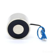
- P20/15 12 V Electromagnet (3 kg holding force) - the 12 V inductive load you will control.
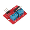
- IRF520 MOSFET Driver Module - for the PWM version (variable strength and hold-current reduction).
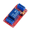
- 1-Channel 5V Relay Module - for the simple on/off version.
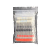
- Diode Kit - use a 1N4007 as the flyback diode across the coil.
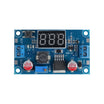
- LM2596 Buck Converter - convenient way to supply 12 V from a laptop or bench supply.
- Tactile Button Kit - for the one-button grab/release input.
- 830-Point Breadboard - fast prototyping.
- Dupont Jumper Wires - to connect the Arduino, module, and button.
External
- A 12 V supply (1 A is plenty) and a few steel objects to pick up (washers, a bolt, a bottle cap).
Note: A coil stores energy. When you switch it off, the collapsing magnetic field tries to keep current flowing and produces a voltage spike that can destroy a MOSFET or damage an Arduino. The 1N4007 across the coil (band/cathode toward +12 V) gives that current a safe path. Never run this circuit without it.
Step-by-Step Guide
Step 1 - Know your magnet
Goal: Set expectations before wiring.
What to do: The P20/15 draws about 0.25 A at 12 V (3 W) and holds up to 3 kg, but only against a flat, clean steel face in full contact. A washer with a thin paint layer might hold at a fraction of that; a curved bolt less still. Aluminum, brass, and stainless (most grades) do not stick. The coil will warm up if left on for minutes; that is normal, and the hold-current trick later helps keep it cooler.
Expected result: You understand what it will and will not lift, and why surface contact matters.
Step 2 - Option A: Relay (simple on/off)
Goal: Wire the quickest on/off control method.
What to do: Relay module wiring: VCC to 5V, GND to GND, IN to D9. Magnet wiring: 12 V supply + to relay COM, relay NO to magnet wire 1, magnet wire 2 to 12 V supply -. Put the diode across the magnet (band toward the COM side / +12 V side). Connect supply - to Arduino GND as well. Button: D2 to GND.
Expected result: The relay clicks and the magnet grips. This version is on/off only (do not use PWM through a relay).
Step 3 - Option B: IRF520 MOSFET (PWM control)
Goal: Enable silent switching and variable current using PWM.
What to do: IRF520 module control wiring: SIG to D9, VCC to 5V, GND to GND. Power side: VIN+ to 12 V +, VIN- to 12 V - (and to Arduino GND). Connect the magnet across the module’s V+ and V- output terminals, with the 1N4007 across the magnet (band toward V+). Use this option for the full sketch in the next step.
Expected result: No clicking sound, and analogWrite() controls magnet strength.
Step 4 - Upload the sketch (grab, hold, soft release)
Goal: Implement one-button toggle control with a two-stage grab and a soft release.
Code:
const int MAG = 9;            // IRF520 SIG (PWM). For the relay: replace analogWrite with digitalWrite.
const int BTN = 2;
const int HOLD_PWM = 200;     // ~78 % duty while holding: cooler coil, still plenty of grip
bool holding = false;

void setup() {
  pinMode(MAG, OUTPUT); analogWrite(MAG, 0);
  pinMode(BTN, INPUT_PULLUP);
  Serial.begin(9600);
  Serial.println("press the button to grab / release");
}

void loop() {
  static bool was = true;
  bool now = digitalRead(BTN);
  if (!now && was) {                               // button just pressed
    holding = !holding;
    if (holding) {
      analogWrite(MAG, 255);                       // full power to pull the object in
      delay(300);
      analogWrite(MAG, HOLD_PWM);                  // then back off to hold
      Serial.println("HOLDING");
    } else {
      for (int p = HOLD_PWM; p >= 0; p -= 10) {     // soft release: no bang, no bounce
        analogWrite(MAG, p); delay(20);
      }
      Serial.println("RELEASED");
    }
    delay(50);                                     // debounce
  }
  was = now;
}
What to do: Upload the sketch. Hold a steel washer under the magnet face and press the button.
Expected result: The washer snaps to the magnet and stays; press again and it drops gently after a short fade. You can try HOLD_PWM at 120 and observe that many objects still hold, showing how much current margin you have.
Step 5 - Apply it to a mechanism
Goal: Turn the demo into a useful actuator for projects.
What to do: Bolt the magnet to a servo arm or robot arm for a simple pick-and-place (grab, move, release). Mount it in a cabinet door with a steel strike plate for a keypad-or-RFID magnetic catch (fail-safe: no power, no lock). Drop a steel ball on command for timing experiments. If you need confirmation that an object is attached before moving, add a hall sensor next to the face.
Expected result: You have a one-wire actuator you can reuse whenever “hold it, then let go” is the job.
Conclusion
You built an Arduino Uno controlled 12 V holding electromagnet driver using either a relay for simple on/off or an IRF520 MOSFET module for PWM strength control. With the flyback diode in place, you can add a full-power grab, a reduced-power hold to cut heat, and a soft release for smoother motion.
Want the exact parts used in this build? Grab them from ShillehTek.com. If you want help customizing this project or building something for your product, check out our IoT consulting services.
Credits
All photos and images in this tutorial are credited to RobotGeek Projects Team on Hackster.io (CC0). The original guide by the RobotGeek Projects Team served as the reference for this ShillehTek version. We thank them for their excellent work in the maker community.





.png?v=25000753014097803521791168436)

.png?v=68677308723310773341791168436)


