

Project Overview
Arduino Nano + WS2812B Monitor Ambilight: This project uses an Arduino Nano to receive Prismatik screen color data over the Adalight protocol and drive a WS2812B LED strip for real-time ambient backlighting behind your monitor.
Ambient backlighting makes a monitor look bigger, softens the contrast between a bright screen and a dark room, and turns games and films into something closer to a light show. Commercial kits cost a lot for what is really a strip of addressable LEDs and a small amount of code.
In this build the PC does the clever part: Prismatik grabs the screen, averages the colour of each zone along the edges and streams one colour per LED over USB. An Arduino Nano listens for those frames using the simple Adalight protocol and pushes them to a WS2812B strip stuck around the back of the monitor. The sketch below is written from scratch with FastLED, checks every frame header, caps the power draw and fades out gracefully when the PC stops talking.
- Time: ~2 hours, most of it fitting the strip
- Skill level: Beginner-Intermediate
- What you will build: A screen-synced backlight with up to a few hundred LEDs, an Adalight receiver sketch with frame checking and power limiting, and a tuned Prismatik setup.

Parts List
From ShillehTek
- Arduino Nano V3.0 (pre-soldered) - receives Adalight frames over USB serial and drives the LED strip
- WS2812B LED Strip, 60 LEDs/m, 5 m - addressable LEDs for the ambilight backlight
- Resistor Kit - use a 330 ohm resistor in series with the data line
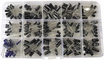
- Electrolytic Capacitor Kit - use a 220 uF capacitor across the strip's supply
- Dupont Jumper Wires - for prototyping and connections to the Nano
External
- A 5 V power supply rated 3-4 A, with a DC barrel-jack terminal adapter
- A Windows, macOS or Linux PC and the free Prismatik software
- Thin hook-up wire, a soldering iron and double-sided tape or adhesive cable clips
Note: each WS2812B can draw up to about 60 mA at full white, so 100 LEDs could ask for 6 A. Screen colours are rarely that bright, and the sketch tells FastLED to stay under 3 A, but always power the strip from its own 5 V supply (never from the Nano's 5V pin or the PC's USB port) and join the supply's ground to the Nano's ground.
Step-by-Step Guide
Step 1 - Plan and Fit the Strip
Goal: LEDs evenly spaced around the back edge, counted side by side.
What to do: Run the strip around the back of the monitor about 1-2 cm in from the edge, so the light lands on the wall rather than shining out sideways. Start at the bottom-left corner (as seen from the front) and go clockwise, with the arrows printed on the strip pointing the way the data travels.
Cut the strip only across the copper pads, and bridge each corner with three short wires: 5V to 5V, GND to GND and DOUT to DIN. Write down how many LEDs ended up on each side. At 60 LEDs per metre a 27-inch monitor takes about 33 along the top and bottom and 18 on each side. Leave a gap at the bottom if the stand is in the way; Prismatik can skip it.
Expected result: One continuous chain of LEDs, and four numbers that add up to your total.
Step 2 - Wire the Nano and the Power

Goal: A clean data signal and a supply that can carry the strip.
What to do: 5 V supply + to strip 5V; supply - to strip GND and Nano GND. Nano D6 to 330 ohm resistor to strip DIN at the first LED.
Put a 220 uF capacitor across 5V and GND where the supply meets the strip (stripe to GND) to absorb the inrush when the LEDs switch on. Connect the Nano to the PC by USB, which powers it and carries the colour data. Leave the strip's 5V unconnected from the Nano's 5V pin.
On long runs (more than about 150 LEDs), also feed 5V and GND into the far end of the strip to stop the colours turning orange at the end.
Expected result: The Nano powered by USB, the strip by its own supply, with a common ground.
Step 3 - The Adalight Receiver Sketch
Goal: Upload an Arduino sketch that validates Adalight frames and drives the LED strip with power limiting.
Code:
#include <FastLED.h>

const int NUM_LEDS = 90;               // total LEDs around your monitor (must match Prismatik)
const int DATA_PIN = 6;
const long BAUD = 115200;              // Prismatik's default Adalight speed
const uint8_t MAX_BRIGHTNESS = 160;    // 0-255: caps glare and current

CRGB leds[NUM_LEDS];

int readByte() {                       // wait up to one second for the next byte
  unsigned long start = millis();
  while (!Serial.available()) {
    if (millis() - start > 1000) return -1;
  }
  return Serial.read();
}

void idle() {                          // no frames arriving: fade gently to off
  fadeToBlackBy(leds, NUM_LEDS, 20);
  FastLED.show();
}

void setup() {
  FastLED.addLeds<WS2812B, DATA_PIN, GRB>(leds, NUM_LEDS);
  FastLED.setBrightness(MAX_BRIGHTNESS);
  FastLED.setMaxPowerInVoltsAndMilliamps(5, 3000);   // never ask the supply for more than 3 A
  fill_solid(leds, NUM_LEDS, CRGB(40, 40, 40));       // power-on test: dim white
  FastLED.show();
  Serial.begin(BAUD);
  Serial.print("Ada\n");               // Adalight greeting
}

void loop() {
  // 1. Every frame starts with the magic word "Ada"
  static const uint8_t magic[3] = {'A', 'd', 'a'};
  for (int i = 0; i < 3; ) {
    int b = readByte();
    if (b < 0) { idle(); return; }
    i = (b == magic[i]) ? i + 1 : (b == 'A' ? 1 : 0);
  }

  // 2. Header: LED count minus one (high byte, low byte) and a checksum
  int hi = readByte(), lo = readByte(), chk = readByte();
  if (hi < 0 || lo < 0 || chk < 0 || chk != (hi ^ lo ^ 0x55)) return;   // corrupt: wait for the next frame
  int count = ((hi << 8) | lo) + 1;

  // 3. Three bytes (red, green, blue) per LED
  for (int i = 0; i < count; i++) {
    int r = readByte(), g = readByte(), b = readByte();
    if (b < 0) return;
    if (i < NUM_LEDS) leds[i] = CRGB(r, g, b);
  }
  FastLED.show();
}
What to do: Install FastLED from the Library Manager, set NUM_LEDS to your total from Step 1 and upload with the board set to "Arduino Nano" (choose the "Old Bootloader" processor option if the upload times out).
Expected result: The whole strip lights a dim white (every LED working, the chain unbroken). After a second with no PC software running, it slowly fades out.
Step 4 - Set Up Prismatik
Goal: The PC streaming screen colours to the strip.
What to do: Download Prismatik from the actively maintained open-source fork (psieg/Lightpack on GitHub) and run its setup wizard. Choose Adalight as the device, select the Nano's serial port, keep 115200 baud and enter the same number of LEDs as NUM_LEDS.
In the zone-placement page, enter your LED counts for each side, the starting corner (bottom-left) and the direction (clockwise), then let the wizard light each zone so you can confirm it matches. If red and blue come out swapped, change GRB in the sketch to RGB and upload again.
Expected result: Drag a colourful window around the screen and the light behind the monitor follows it, zone by zone.
Step 5 - Tune It
Goal: Smooth, pleasant light rather than a flickering disco.
What to do: In Prismatik, add a little smoothing so scene cuts fade instead of snapping, and keep the update rate around 25-30 frames per second. At 115200 baud a 90-LED frame takes about 24 ms to send, so asking for more just drops frames.
Lower the overall brightness for night viewing and raise saturation slightly if the light looks washed out. Use the mood-lamp mode for a calm single colour when you're not watching anything. If the far end of the strip looks dimmer or yellower than the start, add the second power feed from Step 2.
Expected result: Light that extends the picture onto the wall and is easy on the eyes in a dark room.
Step 6 - Upgrades
Goal: Beyond the desk monitor.
What to do: Because the sketch speaks plain Adalight, other software can drive it too: HyperHDR or Hyperion.ng running on a small Linux box with a USB HDMI capture card will sync a TV to any input, including consoles. For a wireless version, an ESP32 running WLED accepts the same screen data over Wi-Fi.
Mount a second strip under the desk and drive it from another pin for a matching glow, or add a push button that switches between screen sync and a fixed colour.
Expected result: A backlight system you can grow from one monitor to the whole room.
Conclusion
An Arduino Nano, a few metres of WS2812B strip and a 5 V supply turn Prismatik's screen analysis into a real ambilight: the PC measures the colours along each edge, the Adalight protocol carries them over USB, and the Nano's checked, power-limited FastLED sketch paints them onto the wall. It costs a fraction of a commercial kit and you control every setting.
Want the exact parts used in this build? Grab them from ShillehTek.com. If you want help customizing this project or building something for your product, check out our IoT consulting services.
Photo and diagram credit: Quartz Components on Hackster.io.






.png?v=25000753014097803521791168436)

.png?v=68677308723310773341791168436)


