

Project Overview
Arduino Nano + HC-SR04 transducers acoustic levitator: In this build, you remove the two 40 kHz transducers from an HC-SR04 module and drive them face-to-face with an L298N so tiny foam beads can float in mid-air on a standing ultrasonic wave.
Sound is a pressure wave, and when two identical waves travel toward each other they form a standing wave: fixed points of almost no pressure variation (nodes) separated by half a wavelength. A light enough object placed in one of those nodes gets pushed back into it from both sides and can hover. At 40 kHz the wavelength in air is about 8.6 mm, so nodes sit about 4.3 mm apart, which works well for small polystyrene beads. This build drives both transducers from an L298N H-bridge and generates a crystal-accurate 40.000 kHz pair of opposite square waves using the Nano's Timer1 hardware PWM, leaving the processor free and letting you fine-tune frequency over USB.
- Time: ~1.5 hours
- Skill level: Intermediate (some desoldering)
- What you will build: A small acoustic levitator that holds one or more foam beads in mid-air between two ultrasonic transducers, with frequency fine-tuning and on/off control from the Serial Monitor.

Parts List
From ShillehTek
- Arduino Nano V3.0 (pre-soldered) - generates the precise 40 kHz push-pull drive using Timer1 hardware outputs
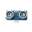
- HC-SR04 Ultrasonic Sensor Module - source of the two 40 kHz transducers used for levitation
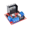
- L298N Motor Driver Board - H-bridge driver to apply a larger voltage swing across the transducers
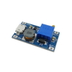
- MT3608 Boost Converter - boosts 5 V from a USB charger up to about 9 V for the L298N supply
- 400-Point Breadboard - quick prototyping for the Nano-to-driver wiring
- Dupont Jumper Wires - connects the Nano, boost converter, and driver inputs
External
- A 5 V USB charger and cable for the boost converter (or a 9 to 12 V DC adapter instead of the MT3608)
- Polystyrene foam beads 1 to 3 mm across (crumble a piece of packing foam)
- Something to hold the transducers rigidly face to face: a 3D-printed stand, two blocks of wood on a ruler, or a clothes peg
- Thin wire, a soldering iron, and a desoldering pump or braid
Note: 40 kHz is above the range of human hearing, but the transducers can still produce an audible whine and a strong field right at the face. Do not hold them against your ear, and keep the driver supply at 12 V or below. The small HC-SR04 transducer cans are not designed for more.
Step-by-Step Guide
Step 1 - Harvest the Transducers
Goal: Two free-standing 40 kHz transducers on long leads.
What to do: The HC-SR04 carries two silver cans marked T (transmitter) and R (receiver). Both are 40 kHz piezo transducers, so both can be used as emitters here. Desolder them with a pump or braid (or snip the legs close to the board), then solder about 15 cm of thin wire to each, noting which leg goes to which wire so both can be connected the same way round. The original build also removed the protective mesh from the front of each can.
Expected result: Two transducers on flexible leads, ready to be mounted facing each other.
Step 2 - Wire the Driver and Power
Goal: Two opposite 40 kHz signals into the H-bridge, and the transducers on its output.

What to do: Feed the MT3608 from the USB charger and turn its trimmer until the output reads 9 V before connecting anything else. MT3608 OUT+ goes to the L298N 12V terminal, OUT- goes to the L298N GND, and that GND must also connect to the Nano GND. Connect Nano D9 to IN1 and Nano D10 to IN2, and leave the ENA jumper fitted so channel A is always enabled.
Connect both transducers in parallel across OUT1 and OUT2, with the same leg of each transducer on the same terminal. Power the Nano from its own USB cable and leave the L298N 5V terminal unconnected. Because the bridge flips the full supply across the transducers every half cycle, they see close to twice the supply voltage peak-to-peak (minus a few volts lost inside the L298N).
Expected result: A 9 V driver supply, two signal wires connected to IN1/IN2, and two transducers connected to OUT1/OUT2 on one H-bridge channel.
Step 3 - Upload the 40 kHz Sketch
Goal: Generate two opposite 40 kHz square waves on D9 and D10 using Timer1 hardware.
Code:
// Two opposite 40 kHz square waves on D9 (OC1A) and D10 (OC1B), made by Timer1 hardware.
// Serial Monitor at 115200: '+' raises the frequency, '-' lowers it, '0' off, '1' on.

uint16_t top = 399;                     // 16 MHz / (399 + 1) = 40.000 kHz

void applyFrequency() {                 // change the period without a glitch
  TCCR1B &= ~_BV(CS10);                 // pause the timer
  ICR1 = top;                           // period
  OCR1A = (top + 1) / 2;                // 50 % duty on both outputs
  OCR1B = (top + 1) / 2;
  TCNT1 = 0;
  TCCR1B |= _BV(CS10);                  // run at 16 MHz, no prescaler
}

void outputs(bool on) {                 // connect or release D9/D10
  if (on) {
    TCCR1A |= _BV(COM1A1) | _BV(COM1B1) | _BV(COM1B0);   // OC1A normal, OC1B inverted
  } else {
    TCCR1A &= ~(_BV(COM1A1) | _BV(COM1B1) | _BV(COM1B0));
    PORTB &= ~(_BV(PB1) | _BV(PB2));    // both inputs low: the bridge goes quiet
  }
}

void printFrequency() {
  Serial.print(F("Frequency: "));
  Serial.print(16000000.0 / (top + 1), 0);
  Serial.println(F(" Hz"));
}

void setup() {
  Serial.begin(115200);
  pinMode(9, OUTPUT);                   // to L298N IN1
  pinMode(10, OUTPUT);                  // to L298N IN2
  TCCR1A = _BV(WGM11);                  // mode 14: fast PWM with the period in ICR1
  TCCR1B = _BV(WGM13) | _BV(WGM12);
  applyFrequency();
  outputs(true);
  printFrequency();
}

void loop() {
  if (!Serial.available()) return;      // the hardware does all the work
  char c = Serial.read();
  if (c == '+' && top > 380) top--;      // shorter period = higher frequency (up to ~42 kHz)
  else if (c == '-' && top < 420) top++; // down to ~38 kHz
  else if (c == '0') { outputs(false); Serial.println(F("Off")); return; }
  else if (c == '1') { outputs(true); Serial.println(F("On")); return; }
  else return;
  applyFrequency();
  printFrequency();
}
What to do: Upload to the Nano (board: Arduino Nano). If the upload times out, choose the Old Bootloader processor option. Open the Serial Monitor at 115200 baud. In fast PWM mode 14, OC1A is set at the start of each period and cleared halfway, while OC1B is inverted, so D9 and D10 are exact mirror images. The H-bridge gets a push-pull drive with no interrupt code.
Expected result: You see Frequency: 40000 Hz in the Serial Monitor and, close to the transducers, a faint hiss or whine.
Step 4 - Align and Levitate
Goal: Create a standing wave strong enough to hold a foam bead.
What to do: Fix the transducers facing each other on the same axis, about 2 to 3 cm apart. Using tweezers, or a piece of paper with a slit in it, slide a 1 to 2 mm foam bead into the gap. If it drops, change the spacing in steps of a millimetre or two. The trap is strongest when the gap is a whole number of half wavelengths (multiples of about 4.3 mm).
Then press + or - a few times in the Serial Monitor. Each step moves the frequency by about 100 Hz, and these transducers respond best within about a kilohertz of their resonance.
Expected result: A bead hovering steadily in the gap. With practice you can stack two or three beads in neighbouring nodes about 4 mm apart.
Step 5 - What is Going On
Goal: Understand the standing wave effect you used.
What to do: Each transducer sends a 40 kHz sound wave toward the other. Where the waves meet, they form a standing wave with pressure nodes every half wavelength, about 4.3 mm at 40 kHz in room-temperature air (speed of sound about 343 m/s, so 343/40,000 is about 8.6 mm). Acoustic radiation force pushes small objects toward those nodes from both sides, and for something as light as polystyrene that force can beat gravity.
This is also why the object has to be smaller than about half a wavelength, and why the trap collapses if the transducers drift out of line or the frequency wanders away from resonance.
Expected result: You can predict where beads will sit and why spacing and frequency matter.
Step 6 - Upgrades
Goal: Extend the concept with more control.
What to do: Drive the second transducer from the L298N's other channel (IN3/IN4) with its own signal, and shift its phase relative to the first. The standing wave, and the beads in it, slide along the axis as the phase changes. Timer1 toggle (CTC) mode with different compare values for OC1A and OC1B is one way to generate two 40 kHz signals with an adjustable phase offset.
Add more transducers in a curved array for a stronger, more stable trap. Designs like that can even hold tiny water droplets.
Expected result: A levitator you can steer, not just watch.
Conclusion
Using an Arduino Nano, two recycled HC-SR04 40 kHz transducers, an L298N driver, and an MT3608 boost converter, you can generate a stable standing wave that floats foam beads in mid-air. The Timer1 technique used here produces a clean, hardware-timed push-pull drive while still allowing on/off control and frequency trimming over Serial.
Want the exact parts used in this build? Grab them from ShillehTek.com. If you want help customizing this project or building something similar for your product, check out our IoT consulting services.
Credits
All photos and images in this tutorial are credited to Ingeimaks (Giovanni Mannara) on Hackster.io (Apache-2.0 license). The original guide by Giovanni Mannara served as the reference for this ShillehTek version. We thank them for their excellent work in the maker community.





.png?v=25000753014097803521791168436)

.png?v=68677308723310773341791168436)


