EMG Muscle Signal Sensor Module Kit for Arduino, Raspberry Pi & Robotics

SKU ST-XW5QXKVTFTDU

$14.99 USD Shipping & tax calculated at checkout
In stock· Order by 3pm ET and it ships today

EMG Muscle Sensor V3.0 kit with adjustable gain. Recommended regulated split ±5 V supply; nominal 0–5 V SIG envelope. See the manual for wiring and ADC compatibility.

Bulk eligible

Mix any Bulk eligible products — discount applies to your total quantity across the cart.
Auto-applied at checkout
Buy 5+ $14.24 each Save 5%
Buy 10+ $13.49 each Save 10%
View all bulk eligible products →
  • Free Ground Shipping U.S. orders $35+
  • Ships from USA Worldwide via DHL
  • 30-day returns Free defect replacement
  • 7-day support Fast email replies
Frequently bought together
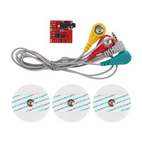
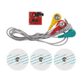
EMG Muscle Sensor V3.0 kit with a red adjustable-gain board, gray three-lead electrode cable and three round electrode pads. EMG Muscle Signal Sensor Module Kit for Arduino, Raspberry Pi & Robotics ★★★★★ (2) $14.99 This item
Total for 4 items
$29.96

Products related to this item

Product Overview

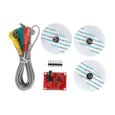
EMG Muscle Sensor V3.0 kit for muscle-activity experiments, robotics and biofeedback projects. Includes a red adjustable-gain board without corner mounting holes, a three-lead electrode cable and three disposable pads. The board has +Vs, GND and −Vs supply connections, plus analog SIG output and GND.

Recommended operating setup: Regulated split ±5 V: +5 V to +Vs, 0 V to GND, and −5 V to −Vs. SIG has a nominal 0–5 V design envelope with this supply; check the ADC input limits and use appropriate scaling/protection for 3.3 V inputs. Follow the current V3.0 manual for wiring, isolation and the evidence behind this recommendation.

This is researched operating guidance for the shown V3.0 layout, not a factory-certified minimum/maximum rating. Do not use the older two-9 V battery or single 3.3–5 V controller-supply examples. For maker and educational use, not medical diagnosis.

Frequently asked questions

Current stock uses the Muscle Sensor V3.0 layout with an adjustable Gain trimmer and no corner mounting holes. Check the current photos and the labels on your board; older layouts may differ.
Use the recommended regulated split ±5 V setup: +5 V to +Vs, 0 V to GND, and −5 V to −Vs. Follow the manual for polarity, isolation and ADC checks. The earlier two-9 V battery and single 3.3–5 V controller-supply examples remain withdrawn. This is an operating recommendation; a factory-certified wider range or absolute maximum is not established.
SIG has a nominal 0–5 V design envelope with the recommended split ±5 V supply. Check the exact ADC input limits and use appropriate scaling/protection for 3.3 V inputs. Raspberry Pi computer GPIO needs an external ADC. Follow the manual for the complete isolated setup.
The current board has labeled connection pads. Check the supplied connections and current manual before wiring; do not assume it is a VCC/GND/SIG-only module or that headers are pre-soldered.
A microcontroller can use a compatible measured analog signal to make control decisions. Complete the electrical checks first, then calibrate thresholds with the final hardware, gain and electrode placement.
Calibrate each channel and collect data with the final setup. Electrical response, gain range and bandwidth have not been verified as identical between revisions.
Disconnect power and electrodes and do not power the board again. Contact admin@shillehtek.com with your order number and clear board photos so we can help.

Have other questions?

Chat with our US-based team — we usually reply fast.

Features & Specs

Current V3.0 layout Red board with an onboard Gain trimmer and no corner mounting holes.

Analog SIG output Nominal 0–5 V rectified/smoothed design envelope at the recommended supply. Actual swing depends on signal, gain and amplifier headroom. Verify ADC compatibility; scale/protect 3.3 V inputs.

Supply connections Recommended regulated split ±5 V: +5 V to +Vs, 0 V to GND, −5 V to −Vs. Research-based operating guidance; factory-certified minimum/maximum ratings are not established. Do not use the older two-9 V or single controller-rail examples.

Electrode connection Supplied three-lead snap electrode cable and three disposable pads. Lead colors alone do not identify measurement and reference functions.

Controller interface Arduino, ESP32 and Pico require a verified compatible analog input. Raspberry Pi requires an external ADC. Controller voltage alone does not establish compatibility.

Calibration Set up and calibrate every channel with the final hardware and electrode placement. Electrical equivalence with older layouts has not been verified.

Kit and intended use One sensor board, electrode cable and pads. Maker, STEM and robotics experiments; not a medical device.

Documents

Full Product Manual EMG Muscle Sensor V3.0 Manual | ShillehTek In-depth setup guide with wiring, code examples, and troubleshooting.

Related Tutorials

Related Videos

Customer Reviews