Overview
Solder-seal connectors make a soldered, insulated, sealed wire splice in a single step. Each one is a clear heat-shrink sleeve with a ring of low-temperature solder in the middle and a colored sealing ring near each end. Overlap two stripped wires inside the sleeve and heat it: the solder melts into the strands, the sleeve shrinks around the joint, and the rings melt to close off the ends.
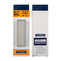
The kit holds 60 connectors in four sizes — 20 red, 20 blue, 15 white, and 5 yellow — in a plastic storage box. The color tells you the wire size the connector is made for, and red is the one most electronics work uses, because it covers typical 22 AWG hookup wire. No soldering iron and no crimp tool are needed, only a heat gun.
The supplier does not publish a wire-size chart or ratings with this listing, so the sizes in this manual follow the color code that is standard for these connectors. Check any chart supplied with your kit, and make one practice splice on scrap wire before working on a harness you care about.
At a Glance
Specifications
| Parameter | Value |
| Connector type | Solder-seal heat-shrink butt connectors |
| Kit contents | 60 connectors in a plastic storage box |
| Red | 20 pieces — typically 22–18 AWG |
| Blue | 20 pieces — typically 16–14 AWG |
| White | 15 pieces — typically 26–24 AWG |
| Yellow | 5 pieces — typically 12–10 AWG |
| Size chart status | Standard color code for this connector type; not published by the supplier for this kit |
| Solder | Low-temperature ring, typically melting from about 138 °C |
| Sealing | Hot-melt adhesive rings at both ends |
| Heat source | Hot-air gun (a hair dryer is not hot enough; a lighter is not recommended) |
| Voltage / current rating | Not published |
| Reusable | No — single use |
Wiring Guide
A solder-seal splice has two things to get right: the bare conductors must overlap directly under the solder ring, and the heat has to stay on the middle until the solder actually flows. The sleeve shrinking is not the sign that you are done — the solder ring collapsing into the strands is.
Making a Splice
| Step | What To Do | Notes |
|---|---|---|
| 1. Choose the size | Match the connector color to the wire gauge | See the Sizes tab |
| 2. Strip both wires | Remove about 6–10 mm of insulation | Use the shorter end of that range for the small white size |
| 3. Slide it on | Push the connector over one wire, clear of the joint | Like heat-shrink, it has to go on first |
| 4. Overlap the ends | Lay or mesh the bare ends together and center the solder ring over them | The colored rings should sit over insulation, not bare wire |
| 5. Heat | Heat the solder ring until it melts and flows into the strands, then warm each end until the colored rings melt | Rotate the joint or move the gun so it heats evenly |
| 6. Cool and test | Leave it still until cool, then pull firmly | Do not tug while the solder is still liquid |
Matching Color to Wire Size
This is the standard color code for solder-seal connectors. It is not printed in the listing for this kit, so confirm it against any chart in your box.
| Color | Typical Wire Range | In This Kit | Common Use |
|---|---|---|---|
| White | 26–24 AWG | 15 | Thin signal and sensor wires |
| Red | 22–18 AWG | 20 | Hookup wire, 22 AWG wire sets, small power leads |
| Blue | 16–14 AWG | 20 | Heavier power leads |
| Yellow | 12–10 AWG | 5 | Thick supply cables |
Heating Technique
| Topic | Guidance | Why |
|---|---|---|
| Tool | Hot-air gun, starting on a medium setting | Full heat straight away can scorch the sleeve before the solder melts |
| Distance | A few cm from the nozzle, keeping the joint moving | Even heating melts the solder without burning the tubing |
| Order | Middle first, then the two ends | The solder needs the most heat; the sealing rings melt easily after that |
| What to watch | The solder ring collapses, turns shiny, and wicks into the strands | A shrunken sleeve with an intact solder ring is not a finished joint |
| Nearby parts | Shield nearby wires, plastic parts, and above all batteries | The same hot air softens insulation and damages cells |
Limits and Checks
| Topic | Guidance | Why |
|---|---|---|
| Current and voltage | Use for low-voltage wiring within the wire’s own capacity | No electrical rating is published for this kit |
| Heat | Keep finished joints away from hot zones | The solder is a low-melting alloy, and similar parts are typically rated to about 125 °C |
| Strain and vibration | Support the wire near the splice | A soldered splice is rigid and should not carry the cable’s weight |
| High-current cables | Use crimped lugs instead | Solder-seal splices are not suited to battery cables or structural joints |
| Inspection | Solder flowed, both rings sealed, pull test passed | If any one fails, cut it out and make a new splice |