


Project Overview
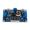
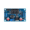
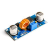
XL4015 buck converter module: In this build, you will turn an XL4015 5A CC/CV buck converter (with onboard voltmeter and current display) into an adjustable 1.25V to 36V DIY bench power supply for regulated, current-limited DC output.
This guide wires the XL4015 into an enclosure with binding posts, walks through constant-voltage (CV) and constant-current (CC) adjustment, and highlights a few practical XL4015 use cases.
- Time: About 15 to 30 minutes (not including enclosure cutting/printing)
- Skill level: Beginner to Intermediate
- What you will build: A compact bench-style power supply powered by a 12V to 24V DC brick with adjustable voltage and current limiting
Parts List
From ShillehTek
- Arduino Nano V3.0 - optional if you want to add USB monitoring of voltage/current
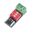
- PDSink PD Decoy Board - optional for a USB-C-powered bench PSU (pull 9V/12V/15V/20V and feed the XL4015)
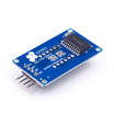
- TM1637 4-Bit Display - optional alternative for displaying voltage/current
- DuPont Wires - helpful for internal wiring and prototyping add-ons
External
- XL4015 5A 75W buck converter module (variant with onboard voltmeter / current meter and CC/CV adjustment)
- 24V DC laptop brick or AC-to-DC power supply (rated for 5A+ if you want full output capability)
- Project enclosure with binding-post cutouts (or one you can drill/cut)
- Two banana-plug binding posts (red and black)
- Inline 5A blade fuse on the output (recommended for safety)
Note: XL4015 boards vary by seller. Confirm your specific module has CC (current limit) adjustment and the same terminal labeling before wiring it into an enclosure.
Step-by-Step Guide
Step 1 - Choose XL4015 for higher current projects
Goal: Understand when the XL4015 is a better choice than smaller buck converters.
What to do: If your project needs more than about 2A continuous, the XL4015 is a strong option. Compared with common LM2596 and MP1584 modules, it supports higher continuous current and typically offers better efficiency at higher loads.

| LM2596 | MP1584 | XL4015 | |
|---|---|---|---|
| Max current (continuous) | 2A | 3A | 5A |
| Max input voltage | 40V | 28V | 38V |
| Switching freq | 150kHz | 1.5MHz | 180kHz |
| Efficiency (24V to 12V) | ~80% | ~93% | ~96% |
| Onboard CC/CV? | No | No | Yes (some variants) |
| Cost | $1.50 | $2 | $4 to $6 |
Expected result: You know why the XL4015 is commonly used when you need higher current and want CC/CV adjustment in a low-cost module.
Step 2 - Identify the XL4015 terminal wiring
Goal: Map each terminal to your input power and output binding posts.
What to do: Most XL4015 boards expose screw terminals for input and output, plus an optional enable (EN) pin on some variants. Wire your DC brick to IN+/IN-, and wire your front-panel binding posts to OUT+/OUT-.
Code:
IN+  <-- 24V DC from your power brick
IN-  <-- GND from power brick
OUT+ --> red binding post
OUT- --> black binding post
EN   (optional) <-- pull HIGH or to IN+ to enable
Expected result: You have a clear wiring plan for connecting input power and the bench output terminals.
Step 3 - Set CV (constant voltage) output
Goal: Adjust the output voltage to a known target before connecting a load.
What to do: Use the CV potentiometer (often labeled V-ADJ) to set the output voltage with no load connected.

- Power up the input.
- Put a multimeter on OUT+ and OUT-.
- Turn the V-ADJ pot until the meter reads your target voltage (for example 5.0V or 12.0V).
- Confirm the onboard display matches your meter (typically within about 50mV).
Expected result: The output voltage is stable at your target value and matches your multimeter reading closely.
Step 4 - Set CC (constant current) limit
Goal: Configure the current limit so the supply can protect loads and support CC/CV behavior.
What to do: On the XL4015 variant with onboard voltmeter/current display, use the second potentiometer (often labeled I-ADJ or CC) to set the current limit.
- Short OUT+ to OUT- through your multimeter set to 10A DC current.
- Turn the I-ADJ pot until the meter reads your target current (for example 1.5A).
- Remove the short. The supply will deliver up to that current. Above the limit, voltage will drop to maintain the set current.
Expected result: The output current clamps at the value you set when the output is shorted through the meter, confirming CC limiting works.
Step 5 - Install the module into an enclosure
Goal: Make the XL4015 module bench-friendly and safer to use.
What to do: Mount the bare PCB in a project box and add proper panel connectors so it behaves like a small bench power supply.
- 3D-print or buy a project box with a window for the LED display.
- Add front-panel binding posts (red and black).
- Add a panel-mount DC barrel jack for the input.
- Add an inline 5A fuse on the output. The XL4015 has protection features, but a fuse provides hard protection.
- Add a power LED (some kits include this onboard).
Expected result: The module is mechanically protected and you have reliable, repeatable front-panel connections for input and output.
Step 6 - Apply the XL4015 to other common builds
Goal: Understand other practical scenarios where CC/CV and 5A capability are useful.
What to do: Consider these additional use cases where an XL4015 is handy to keep in your parts bin.

- Solar-charged 12V system: Use the XL4015 as the buck stage between an MPPT controller and a 12V battery.
- LED strip dimmer: Set the CC limit to control brightness without PWM flicker.
- Battery charger (1S/2S/3S Li-ion): CC plus CV matches lithium charging needs. Calibrate carefully; dedicated chargers are safer.
- Workshop hot-wire foam cutter: 5A at 3V to 6V is useful for cutting foam.
- USB-C laptop charger replacement: Pair with a PDSink board to draw 20V from USB-C PD and convert to 5V/12V/other outputs.
Expected result: You can identify where an adjustable CC/CV buck converter solves real power problems beyond a bench PSU.
Step 7 - Account for heat, ripple, and polarity limits
Goal: Avoid common performance and safety issues when using the XL4015 near its limits.
What to do: Keep these constraints in mind when you design your enclosure and choose loads.
- Heat: At 5A continuous, the XL4015 can get hot enough to burn. Add a small heatsink or active fan if you draw more than 3A for long periods.
- Output ripple: Around 50mV at full load. For sensitive analog circuits (audio, low-noise sensors), add a downstream LC filter.
- Reverse polarity: Many XL4015 boards have no input reverse-polarity protection. Add a Schottky diode in series with IN+ if reverse connection is a concern.
Expected result: You know what to upgrade (cooling, filtering, protection) when you push the XL4015 toward higher current or lower-noise applications.
Conclusion
The XL4015 buck converter module with an onboard voltmeter/current display is a simple way to build an adjustable bench power supply that supports CC/CV behavior and can deliver up to 5A in the right thermal setup. With a DC brick, enclosure, binding posts, and a fuse, it becomes a reliable regulated DC source for everyday bench work.
Want the exact parts used in this build? Grab them from ShillehTek.com. If you want help customizing this project or building something for your product, check out our IoT consulting services.




.png?v=25000753014097803521791168436)

.png?v=68677308723310773341791168436)


