

Project Overview
Teensy 4.0 + GUVA-S12SD UV sensor rechargeable UV index meter: This build uses a GUVA-S12SD true-UV photodiode module and a Teensy 4.0 to calculate a live UV index and render it on an ST7789 color LCD, along with safe sun-exposure time, a battery gauge, and a face graphic that gets redder as UV increases. A TP4056 charging board makes it USB-rechargeable, and a sloped 3D-printed enclosure keeps the sensor pointed at the sky while the screen stays readable.
- Time: A weekend (3D printing + soldering + assembly)
- Skill level: Advanced (soldering, 3D printing, some CAD)
- What you will build: A pocketable, rechargeable UV index meter with a color display.


Parts List
From ShillehTek
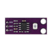
- GUVA-S12SD UV Light Intensity Sensor Module - the heart of the meter
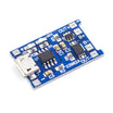
- TP4056 LiPo Charging Board (Micro USB) - with charge/standby LEDs
- Metal Film Resistor Kit - two 10K resistors for the battery voltage divider
- 5x7cm Prototype PCB (3-pack) - the solder board everything mounts to
External
- Teensy 4.0 (any 3.3V Arduino-compatible with a couple of analog pins works with code tweaks)
- ST7789 1.3" color LCD (SPI)
- 3.7V LiPo battery + S7V8F3 3.3V regulator + rocker switch
- Fused quartz plate (UV-transparent sensor window), 1/8" acrylic, M2 screws, 22 AWG wire
- 3D printer, soldering iron, hot glue
Note: The GUVA-S12SD outputs a voltage proportional to UV photodiode current - divide the output voltage by 0.1 and you have the UV index. That one-line conversion is what makes this sensor so pleasant to work with.
Step-by-Step Guide
Step 1 - Design the Circuit
Goal: Understand the power and signal paths.
What to do: The microcontroller drives the ST7789 over 4-wire SPI (SCL, SDA, RES, DC). The GUVA-S12SD runs from 3.3V and feeds one analog input; its output equals 4.3× the photodiode current in µA, so UV index = output voltage ÷ 0.1.
Power flows from the LiPo through the TP4056 (for charging) and a rocker switch into the 3.3V regulator. One more analog pin (A3) watches the battery through a 2:1 voltage divider made of two 10K resistors. The divider is required because a full LiPo sits at 4.2V, above the 3.3V analog pin limit.

Expected result: A clear schematic before any soldering.
Step 2 - Load the Firmware
Goal: Understand the code you are flashing.
What to do: The firmware uses the Adafruit GFX and ST7789 libraries (install via the IDE's Library Manager). The main loop reads battery percentage and UV index once per second and only redraws the parts of the screen that changed to eliminate display lag:
Code:
#include "TFT_display.h"
#include "battery.h"
#include "UV_sensor.h"
float last_percent = 100;
float last_index = 100;
float percent_now;
float index_now;

void setup(void) {
  Serial.begin(9600);
  init_screen();
}

void loop() {
  percent_now = bat_percentage();
  index_now = UV_index();

  // only update the screen if a reading changed
  if (percent_now != last_percent) {
    display_battery(percent_now);
    last_percent = percent_now;
  }
  if (index_now != last_index) {
    display_texts(index_now);
    display_pic(index_now);
    last_index = index_now;
  }
  delay(1000);
}
The signature feature is the sunburn-simulating face: the bitmap's red channel is scaled by the UV index. Each 16-bit pixel packs red in the top 5 bits, so the code extracts it, boosts it proportionally to the index, clamps it, and writes it back:
Code:
uint16_t adjust_redness(uint16_t color, int index) {
  // color format: RRRRR-GGGGGG-BBBBB
  int r = color >> 11;
  int new_r = r + (r * index / 5);
  if (new_r > 0b11111) {
    new_r = 0b11111; // don't overflow the 5 red bits
  }
  uint16_t new_color = (color & 0b0000011111111111) | (new_r << 11);
  return new_color;
}
Battery percentage comes from reading the divided battery voltage and running it through a piecewise-linear LiPo discharge curve. It is not lab-grade, but consistently within about ±10%.

Expected result: Firmware compiled and flashed; the full source and CAD files are in the original author's repository (see credits).
Step 3 - Print the Enclosure
Goal: A dustproof, ergonomic case.
What to do: Print the main housing and back plate in PLA (0.15 mm layers, no supports, display opening face-down). The top is sloped at about 42 degrees so you can read the screen comfortably while the sensor opening points straight up.
An acrylic window protects the LCD, and a fused quartz plate covers the sensor. Quartz passes about 90% of UV, so the sensor still reads accurately behind it.


Expected result: Printed parts ready for assembly.
Step 4 - The Details That Make It Usable
Goal: Switch, charging port, and anti-loss touches.
What to do: The rocker switch sits recessed into the case so it cannot toggle accidentally in a bag. The micro-USB charging port hides behind a tiny snap-fit plug printed at finer 0.1 mm resolution for a crisp fit. The plug is tethered to the case with a short wire so it does not get lost.


Expected result: All mechanical details accounted for before assembly.
Step 5 - Solder the Electronics
Goal: Fit everything onto one small solder board.
What to do: Solder the microcontroller and regulator to the underside of the board and the TP4056 on top along the last row. The LCD and UV sensor get direct wire runs (no room for Dupont connectors).
Important sequencing tip: push the rocker switch into the housing before soldering its wires, or it will not fit through the hole.


Expected result: A compact, working electronics stack.
Step 6 - Assemble the Case
Goal: Put it all together safely.
What to do: Hot-glue the quartz plate and acrylic window into the housing (keep glue off the visible quartz because it would block UV). Screw the sensor and LCD down with M2×5mm screws, then the solder board with M2×10mm.
Put electrical tape between the LiPo and the board and trim protruding header pins so nothing can puncture the battery. Tether the USB plug, close the back plate, and screw it shut.


Expected result: A sealed, pocketable UV meter.
Step 7 - Charge and Go
Goal: Keep it running for beach season.
What to do: Pop the port plug and connect micro USB: a red glow means charging, blue means full (courtesy of the TP4056's CHRG and STDBY LEDs). The case is dustproof but not waterproof, so keep it out of the pool. Then take it outside and watch the index.


Expected result: A rechargeable UV companion that tells you when to reapply sunscreen or head for shade.
Conclusion
You built a complete gadget around the GUVA-S12SD: UV sensing converted to a live UV index, an ST7789 color display with dynamic graphics, and LiPo power with USB recharging via a TP4056. The sloped 3D-printed enclosure makes it practical to use outdoors without shading the sensor.
Credits: the photos and the original project inspiration came from Instructables by Bill Yen (billyen33).
Want the exact parts used in this build? Grab them from ShillehTek.com. If you want help customizing this project or building something for your product, check out our IoT consulting services.



.png?v=25000753014097803521791168436)

.png?v=68677308723310773341791168436)


