

Project Overview
ESP32 deep sleep with timer wake-up: In this project, you will use an ESP32 timer wake-up (deep sleep) cycle to wake, blink an LED, print the boot count and wake reason, then go back to sleep so your battery-powered node can run far longer.
An ESP32 awake and connected burns 80 to 160 mA; in deep sleep it sips around 10 uA. The difference between a project that dies overnight and one that runs for months is learning to put the chip to sleep between jobs and let a timer wake it up.
This guide builds the simplest possible version: wake, blink, count boots, sleep. It also explains what survives sleep, what does not, and how to structure real sensor loggers around it.
- Time: ~30 minutes
- Skill level: Beginner to Intermediate
- What you will build: An ESP32 that wakes every 10 seconds, blinks, reports its boot count and wake reason, and goes back to sleep as a starting point for battery-powered ESP32 nodes.

Parts List
From ShillehTek
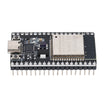
- ESP32 38-Pin Dev Board (CP2102, USB-C) - the ESP32 board used for the deep sleep timer wake-up demo
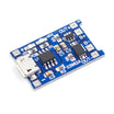
- TP4056 Li-ion Charger Board - to run the finished node from a cell
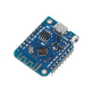
- ESP8266 D1 Mini - the same idea works here with a D0 to RST jumper (see Step 5)
- 400-Point Breadboard - optional for prototyping
- Dupont Jumper Wires - optional for prototyping
External
- An 18650 cell and holder (for the battery version)
- A USB power meter or multimeter to see the current drop
Note: Deep sleep is a reset in disguise. When the ESP32 wakes, setup() runs again from the top and normal variables are wiped. Only RTC memory (variables tagged RTC_DATA_ATTR) survives, which is how you keep a counter or last reading across sleeps.
Step-by-Step Guide
Step 1 - Set Up the Board
Goal: Get the ESP32 ready to flash.
What to do: Install the ESP32 board package in the Arduino IDE (Boards Manager, search for "esp32" by Espressif). Select your dev board and plug it in over USB-C. The onboard blue LED on GPIO 2 is all the hardware this first version needs.
Expected result: A COM port appears and an ESP32 board is selected in the IDE.
Step 2 - Understand the Three Sleep Tools
Goal: Know the core API calls before using them.
What to do: There are three key calls: esp_sleep_enable_timer_wakeup(us) arms the timer, esp_deep_sleep_start() cuts power to the CPU, and after waking esp_sleep_get_wakeup_cause() tells you why you are running. Everything else is ordinary Arduino code that happens to live entirely in setup().
Expected result: A mental model where setup() is the whole program and loop() never runs.
Step 3 - Upload the Sketch
Goal: Make the ESP32 wake, blink, print status, and return to deep sleep on a timer.
What to do: Upload the sketch below and open the Serial Monitor at 115200 baud.
Code:
#define uS_TO_S 1000000ULL
const int SLEEP_S = 10;                 // seconds asleep between wake-ups
const int LED = 2;                      // onboard LED on most ESP32 dev boards

RTC_DATA_ATTR int bootCount = 0;        // lives in RTC memory, survives deep sleep

void printWakeReason() {
  esp_sleep_wakeup_cause_t r = esp_sleep_get_wakeup_cause();
  switch (r) {
    case ESP_SLEEP_WAKEUP_TIMER: Serial.println("Woke up: timer");        break;
    case ESP_SLEEP_WAKEUP_EXT0:  Serial.println("Woke up: external pin"); break;
    default:                     Serial.printf("Power-on or reset (%d)\n", r); break;
  }
}

void setup() {
  Serial.begin(115200);
  delay(300);                           // give the serial monitor a moment

  bootCount++;
  Serial.printf("Boot #%d\n", bootCount);
  printWakeReason();

  pinMode(LED, OUTPUT);                 // "I'm awake" blink x3
  for (int i = 0; i < 3; i++) {
    digitalWrite(LED, HIGH); delay(150);
    digitalWrite(LED, LOW);  delay(150);
  }

  // --- do the real work here: read a sensor, send a packet, log a value ---

  esp_sleep_enable_timer_wakeup(SLEEP_S * uS_TO_S);
  Serial.printf("Sleeping for %d s...\n", SLEEP_S);
  Serial.flush();                       // make sure the text leaves before power drops
  esp_deep_sleep_start();
}

void loop() {
  // never reached: deep sleep resets the chip and setup() runs again
}
Expected result: Every ~10 seconds you see three blinks, "Boot #N" increases by one, and the wake reason prints as "Woke up: timer".
Step 4 - Measure the Payoff
Goal: Observe the current drop when the ESP32 enters deep sleep.
What to do: Put a USB power meter inline (or a multimeter on the battery lead). Awake with Serial running you will see tens of milliamps. Asleep, the bare ESP32 module can drop to about 10 uA, but a dev board's USB-serial chip and regulator often add a few hundred uA to a couple of mA. For serious battery builds, power the 3V3 pin directly or use a board designed for low sleep current.
Expected result: A current measurement that shows why sleep matters; for example, on an 18650, a node awake 2 seconds every 10 minutes can run for months.
Step 5 - Turn It into a Logger, and the ESP8266 Variant
Goal: Apply the deep sleep pattern to real projects and understand the ESP8266 difference.
What to do: Replace the blink with a sensor read and a quick Wi-Fi or MQTT publish, then sleep for 10 to 15 minutes. Connect, send, sleep is the core pattern. Stash the last reading in an RTC_DATA_ATTR variable and only transmit when it changes to save even more power.
On the ESP8266 D1 Mini the call is ESP.deepSleep(us), and you must jumper D0 to RST so the wake pulse can reset the chip. The ESP8266 timer maximum is around 71 minutes.
Expected result: A battery node design you can reuse for remote sensor projects.
Conclusion
Deep sleep changes how you think about firmware. Instead of a program that runs forever, you write a short job that runs, reports, and disappears until the next alarm. With ESP32 timer wake-up and RTC memory, you can build nodes that only wake long enough to do useful work and then go back to sipping power.
Want the exact parts used in this build? Grab them from ShillehTek.com. If you want help customizing this project or building something for your product, check out our IoT consulting services.
Credits
All photos and images in this tutorial are credited to ronfrtek on Hackster.io. The original guide by ronfrtek served as the reference for this ShillehTek version. We thank them for their excellent work in the maker community.




.png?v=25000753014097803521791168436)

.png?v=68677308723310773341791168436)