

Project Overview
ESP32 Wi-Fi Scanner on a 240×240 ST7789 TFT: Build an ESP32 + ST7789 TFT Wi-Fi scanner that lists nearby networks with RSSI (signal strength), channel, and security type right on a bright color display.
This build refreshes every few seconds and alternates between a signal-strength bar chart and a detailed list. Use it to find less-crowded channels, check coverage room by room, or quickly see what networks are around you.
- Time: ~45 minutes
- Skill level: Intermediate
- What you will build: A handheld Wi-Fi analyzer with RSSI bars, channel and encryption info, and a color-coded strength scale.

Parts List
From ShillehTek
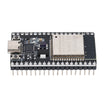
- ESP32 38-Pin Dev Board (CP2102, USB-C) - runs the Wi-Fi scan and drives the TFT over SPI
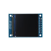
- 1.3" 240×240 ST7789 TFT - color display for bars, SSIDs, and channel/security info (any ST7789 panel works)
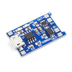
- TP4056 Li-ion Charger Board - optional power solution for a handheld version
- 400-Point Breadboard - quick prototyping and wiring
- Dupont Jumper Wires - connects ESP32 to the TFT module
External
- Optional: a 18650 cell and a small case
Note: RSSI is in dBm and negative: -30 is excellent (next to the router), -67 is the edge of good for video calls, -80 is barely usable. The sketch colors bars green, yellow, and red at those thresholds so you can read coverage at a glance.
Step-by-Step Guide
Step 1 - Wire the TFT
Goal: Connect the ST7789 TFT to the ESP32 using hardware SPI.
What to do: Wire the ST7789 like this: VCC → 3V3, GND → GND, SCL → GPIO 18, SDA → GPIO 23, RES → GPIO 4, DC → GPIO 2, BLK → 3V3 (backlight always on). The 7-pin 1.3" module has no CS pin; the code accounts for that.
Expected result: The display is wired on the ESP32's default SPI pins (SCK 18, MOSI 23).
Step 2 - Install Libraries
Goal: Install the display driver and graphics libraries.
What to do: In the Arduino IDE Library Manager, install Adafruit ST7735 and ST7789 Library and Adafruit GFX Library. The Wi-Fi scanning needs nothing extra because it is included in the ESP32 core.
Expected result: Your Arduino environment is ready to compile the sketch.
Step 3 - Upload the Sketch
Goal: Compile and upload the Wi-Fi scanner firmware to the ESP32.
What to do: Paste the sketch below, select your ESP32 board and port, then upload. If the screen stays blank, note the comment about trying a different SPI mode.
Code:
#include <WiFi.h>
#include <Adafruit_GFX.h>
#include <Adafruit_ST7789.h>

Adafruit_ST7789 tft(-1 /*no CS*/, 2 /*DC*/, 4 /*RST*/);   // hardware SPI: SCK 18, MOSI 23
bool listView = false;

uint16_t colorFor(int rssi) {
  if (rssi > -60) return ST77XX_GREEN;
  if (rssi > -75) return ST77XX_YELLOW;
  return ST77XX_RED;
}

void setup() {
  Serial.begin(115200);
  tft.init(240, 240);                 // blank screen? try tft.init(240, 240, SPI_MODE3)
  tft.setRotation(2);
  tft.fillScreen(ST77XX_BLACK);
  WiFi.mode(WIFI_STA);
  WiFi.disconnect();                  // scan works best when not associated
}

void loop() {
  tft.fillScreen(ST77XX_BLACK);
  tft.setTextColor(ST77XX_WHITE); tft.setTextSize(2); tft.setCursor(0, 0);
  tft.print("Scanning...");
  int n = WiFi.scanNetworks();        // blocks for ~2-3 s
  tft.fillScreen(ST77XX_BLACK);
  tft.setCursor(0, 0); tft.printf("%d networks", n);

  if (!listView) {                    // ---- bar chart: strongest 8 ----
    for (int i = 0; i < n && i < 8; i++) {
      int y = 28 + i * 26;
      int w = map(constrain(WiFi.RSSI(i), -95, -35), -95, -35, 4, 236);
      tft.fillRect(0, y, w, 12, colorFor(WiFi.RSSI(i)));
      tft.setTextSize(1); tft.setTextColor(ST77XX_WHITE); tft.setCursor(0, y + 14);
      tft.printf("%-18.18s %d", WiFi.SSID(i).c_str(), WiFi.RSSI(i));
    }
  } else {                            // ---- list: SSID, channel, security ----
    tft.setTextSize(1);
    for (int i = 0; i < n && i < 16; i++) {
      tft.setCursor(0, 24 + i * 13);
      tft.setTextColor(colorFor(WiFi.RSSI(i)));
      tft.printf("%-16.16s ch%2d %s", WiFi.SSID(i).c_str(), WiFi.channel(i),
                 WiFi.encryptionType(i) == WIFI_AUTH_OPEN ? "open" : "lock");
    }
  }
  WiFi.scanDelete();
  listView = !listView;               // alternate views each refresh
  delay(3500);
}
Expected result: A bar chart of the strongest networks sorted by signal, then a list with channels and open/locked status, alternating every few seconds.
What to do: Watch the screen after upload. The ESP32 scans 2.4 GHz only, so 5 GHz networks will not appear.
Step 4 - Use It Like a Tool
Goal: Turn the scan results into actionable Wi-Fi decisions.
What to do: Walk your house and note where your own SSID drops into yellow; that is where a mesh node or extender may help. In list view, count how many networks sit on each channel; set your router to the emptiest of 1, 6, or 11. Look for open networks you did not expect, like an unsecured printer or camera.
Expected result: You can quickly spot weak coverage areas and crowded channels.
Step 5 - Make It Handheld
Goal: Move from a breadboard prototype to a portable gadget.
What to do: Add a TP4056 and an 18650 cell, a button to freeze the display or switch views manually, and a small case. Optional expansions include logging scans with timestamps to an SD card, or adding a beeper that rises in pitch as your target SSID gets stronger.
Expected result: A compact Wi-Fi scanning tool you can carry room to room.
Conclusion
You built an ESP32 + ST7789 TFT Wi-Fi scanner that makes the local 2.4 GHz radio environment visible, including RSSI, channel, and open/locked status. With a simple bar view and list view, it is fast to check coverage and pick a cleaner router channel.
Want the exact parts used in this build? Grab them from ShillehTek.com. If you want help customizing this project or building something for your product, check out our IoT consulting services.
Credits
All photos and images in this tutorial are credited to Pradeep (CETECH) on Hackster.io. The original guide by Pradeep served as the reference for this ShillehTek version. We thank him for his excellent work in the maker community.




.png?v=25000753014097803521791168436)

.png?v=68677308723310773341791168436)


