

Project Overview
ESP32 + MAX485 Modbus Gateway: Build an ESP32 with a MAX485 RS-485 transceiver that polls a Modbus RTU device and serves the mirrored registers as Modbus TCP over Wi-Fi for Home Assistant, Node-RED, or any SCADA client.
Many industrial sensors, meters, and controllers speak Modbus RTU over a two-wire RS-485 bus, but they are not directly visible on an IP network. In this project, the ESP32 acts as the RTU master on the RS-485 side, polls the device registers on a timer, mirrors them into its own Modbus TCP server, and lets anything on your network read the data using a standard Modbus TCP client. The guide uses an Arduino Nano RTU slave for testing, then shows how to connect the gateway to Home Assistant and Node-RED, plus options for write-through and a wired Ethernet uplink.
- Time: ~1.5 hours
- Skill level: Intermediate
- What you will build: A non-blocking RTU-master / TCP-server gateway on an ESP32 with a mirrored register block, diagnostic counters, and a 500 ms poll, reachable on port 502 from any Modbus TCP client.

Parts List
From ShillehTek
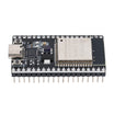
- ESP32 Dev Board (38-pin, CP2102, USB-C) - runs the Modbus RTU master and Modbus TCP server
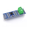
- MAX485 TTL-to-RS485 Module ×2 - one for the gateway and one for the test slave
- Arduino Nano V3 - runs the RTU slave used for testing
- Resistor Kit - 1kΩ + 2kΩ divider for RO, plus 120Ω terminators
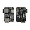
- TTGO T-Internet-POE - optional board for the wired Ethernet version in Step 6
- 830-Point Breadboard - easier wiring and testing on the bench
- Dupont Jumper Wires - connects the ESP32, MAX485, and breadboard
External
- A length of twisted-pair cable for the A/B bus (a strand of Ethernet cable is ideal), and the Modbus RTU device you want to put on the network
Note: The MAX485 is a 5 V part and its RO (receive output) swings to 5 V. The ESP32 inputs are 3.3 V, so RO must go to the ESP32 through a 1kΩ/2kΩ divider. In the other direction, the ESP32 3.3 V on DI and DE is a valid logic high for the MAX485, so no divider is needed.
Step-by-Step Guide
Step 1 - What a Gateway Actually Does
Goal: Understand the gateway architecture before wiring and code.
What to do: Modbus RTU is a master/slave protocol on a serial bus: one master asks, one addressed slave answers, and nobody else talks. Modbus TCP carries the same register model over Ethernet or Wi-Fi, where any client can connect to a server on port 502.
The gateway is both at once. On the RS-485 side it is the single master, polling the slave every half second. On the network side it is a TCP server holding a copy of those registers. Clients read the copy, not the bus, so the bus stays calm no matter how many dashboards are watching, and a slow client cannot hold up the poll.
Expected result: You understand why the sketch mirrors registers instead of forwarding every request.
Step 2 - Wire the Gateway
Goal: Connect the ESP32 to the MAX485 and the RS-485 A/B bus safely.
What to do: Wire the MAX485 (gateway) like this: VCC to ESP32 5V, GND to GND, DI to GPIO17 (TX2), DE and RE tied together to GPIO4, and RO through a 1kΩ resistor to GPIO16 (RX2) with a 2kΩ resistor from GPIO16 to GND (level divider).
For the RS-485 bus, connect A to A and B to B across all devices using the twisted pair. If a device reads garbage, swap A and B because labeling is inconsistent between vendors. For longer runs (a few meters or more), add a 120Ω resistor across A-B at each physical end of the bus. Run a GND wire alongside the pair when devices have separate power supplies.
For the test setup, use the Arduino Nano + MAX485 from the Modbus RTU slave guide, configured as address 1, 9600 baud, 8N1.
Expected result: Two MAX485 modules joined by A, B, and GND, with the gateway DE/RE controlled by ESP32 GPIO4.
Step 3 - The Gateway Sketch
Goal: Run a non-blocking RTU poll loop and mirror values into a Modbus TCP server.
What to do: Install modbus-esp8266 from the Arduino Library Manager (despite the name it supports the ESP32). Fill in your Wi-Fi credentials, then set SLAVE_ID, FIRST_REG, and NUM_REGS to match your device.
Code:
#include <WiFi.h>
#include <ModbusIP_ESP8266.h>   // "modbus-esp8266" library (emelianov) - works on ESP32 too
#include <ModbusRTU.h>

const char* SSID = "YourNetwork";
const char* PASS = "YourPassword";

const int RX2_PIN = 16, TX2_PIN = 17, DE_PIN = 4;   // MAX485: RO -> 16 (via divider), DI <- 17, DE+RE <- 4
const uint8_t  SLAVE_ID  = 1;        // address of the RTU device
const uint16_t FIRST_REG = 0;        // first holding register to mirror
const uint16_t NUM_REGS  = 8;        // how many
const uint32_t POLL_MS   = 500;

ModbusRTU rtu;                        // we are the master on RS-485
ModbusIP  tcp;                        // we are the server on Wi-Fi (port 502)

uint16_t regs[NUM_REGS];
bool busy = false;
uint32_t okCount = 0, errCount = 0;

bool onPoll(Modbus::ResultCode code, uint16_t transactionId, void* data) {   // runs when the RTU reply arrives
  busy = false;
  if (code == Modbus::EX_SUCCESS) {
    okCount++;
    for (int i = 0; i < NUM_REGS; i++) tcp.Hreg(FIRST_REG + i, regs[i]);     // copy into the TCP server
  } else {
    errCount++;
    Serial.printf("RTU error 0x%02X\n", code);                             // 0xE4 = timeout: check A/B, baud, address
  }
  tcp.Hreg(100, okCount & 0xFFFF);     // diagnostics the SCADA side can watch
  tcp.Hreg(101, errCount & 0xFFFF);
  return true;
}

void setup() {
  Serial.begin(115200);
  Serial2.begin(9600, SERIAL_8N1, RX2_PIN, TX2_PIN);   // must match the slave: 9600 8N1 is the Modbus default
  rtu.begin(&Serial2, DE_PIN);                         // the library toggles DE/RE around each frame
  rtu.master();

  WiFi.begin(SSID, PASS);
  while (WiFi.status() != WL_CONNECTED) delay(250);
  Serial.print("Modbus TCP server at "); Serial.println(WiFi.localIP());
  tcp.server();                                        // listen on 502
  tcp.addHreg(FIRST_REG, 0, NUM_REGS);                 // the mirrored block
  tcp.addHreg(100, 0, 2);                              // ok / error counters
}

void loop() {
  static uint32_t lastPoll = 0;
  if (!busy && millis() - lastPoll >= POLL_MS) {
    lastPoll = millis();
    busy = rtu.readHreg(SLAVE_ID, FIRST_REG, regs, NUM_REGS, onPoll);   // non-blocking request
  }
  rtu.task();                                          // drives the serial state machine
  tcp.task();                                          // serves TCP clients
  yield();
}
Expected result: The Serial Monitor prints the gateway IP and then stays quiet. Silence means every poll is succeeding. If you see RTU error 0xE4 every half second, it is a timeout: swap A/B, confirm 9600 8N1 and the slave address, and confirm DE/RE is on GPIO4.
Step 4 - Read It From the Network
Goal: Verify the mirrored Modbus TCP registers are updating.
What to do: From a PC on the same Wi-Fi, use any Modbus TCP client, such as QModMaster (GUI), or run the command below (zero-based addressing) from a terminal:
mbpoll -m tcp -0 -r 0 -c 8 192.168.1.50Change a value on the Nano slave (for example, turn its potentiometer or warm its sensor) and watch register 0 follow within about a second. Also read registers 100 and 101: the ok counter should climb steadily and the error counter should stay unchanged.
Expected result: Live RTU data is visible from any Modbus TCP client on your network.
Step 5 - Into Home Assistant and Node-RED
Goal: Display RS-485 Modbus data in common automation tools without custom integrations.
What to do: Add the example below to Home Assistant configuration.yaml, update the IP, and restart Home Assistant. The sensors should appear and start logging history.
Code:
# Home Assistant configuration.yaml
modbus:
  - name: esp32_gateway
    type: tcp
    host: 192.168.1.50      # the gateway's IP (give it a DHCP reservation)
    port: 502
    sensors:
      - name: Tank Temperature
        address: 0            # mirrored holding register 0
        input_type: holding
        slave: 1
        scale: 0.1            # if the slave stores tenths of a degree
        unit_of_measurement: "°C"
      - name: Gateway Poll Errors
        address: 101
        input_type: holding
        slave: 1
In Node-RED, install node-red-contrib-modbus. Add a Modbus Read node pointing at the gateway (TCP, port 502, FC3, address 0, quantity 8) and wire it to a debug node to see an array of eight values arriving each poll.
Expected result: Your RS-485 Modbus device appears as modern entities and dashboard data in Home Assistant and Node-RED.
Step 6 - Write-Through, More Slaves, Wired Uplink
Goal: Extend the basic read-only mirror into a more complete gateway design.
What to do: For write-through, register an onSetHreg callback on the TCP server for registers you want writable, and inside it call rtu.writeHreg(SLAVE_ID, reg, value). A client writing to the gateway will then change the setpoint on the RS-485 device.
To support more slaves, poll address 1, then 2, then 3 in turn (one request in flight at a time) and mirror each into its own block (0-99, 200-299, etc.), or keep the real unit ID with the library unit parameter.
For a wired uplink, swap the ESP32 for the TTGO T-Internet-POE, replace ModbusIP with the library ModbusEthernet class on the LAN8720 Ethernet link, and you have a PoE-powered gateway suitable for a control cabinet. Note that the PZEM-004T energy meter is Modbus RTU over TTL, so the same master code can read it without a MAX485.
Expected result: A gateway that can be adapted to your device list and network requirements.
Conclusion
This project built an ESP32 + MAX485 Modbus gateway that polls an RS-485 Modbus RTU device and serves a mirrored register map as Modbus TCP over Wi-Fi. With the mirror approach, the RS-485 bus stays stable while Home Assistant, Node-RED, and other Modbus TCP clients read data freely from port 502.
Want the exact parts used in this build? Grab them from ShillehTek.com. If you want help customizing this project or building something for your product, check out our IoT consulting services.
Reference credit: Photos and original reference guide are credited to Nam Nam on Hackster.io.






.png?v=25000753014097803521791038641)

.png?v=68677308723310773341791038641)


