


Project Overview
Arduino + YF-S201 water flow sensor: This project reads the YF-S201 hall-effect pulse output on an Arduino and converts it into real-time liters-per-minute (L/min) and total liters.
The YF-S201 contains a small pinwheel with an embedded magnet. Water flow spins the wheel, and a hall-effect sensor produces pulses proportional to flow rate. The datasheet value is about 450 pulses per liter at moderate flow rates.
This guide wires the sensor to an Arduino, converts pulses to L/min and total liters, and shows common applications like volume dosing for watering, consumption tracking, and basic leak detection.
- Time: 20 to 40 minutes
- Skill level: Beginner
- What you will build: A flow meter that prints L/min to Serial and can be extended to total liters and valve shutoff.
Parts List
From ShillehTek
- Arduino Nano V3.0 - reads the pulse signal and computes flow rate.
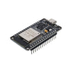
- ESP32 WROOM Dev Board - optional, for WiFi reporting and alerts.
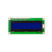
- LCD1602 Display - optional, for a live on-device flow and total readout.
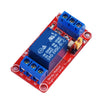
- 1-Channel 12V Relay - optional, to control a 12V solenoid shutoff valve.
External
- YF-S201 water flow sensor (1/2 inch NPS thread, rated 1 to 30 L/min).
- 1/2 inch plumbing adapters to fit your hose or pipe.
- Optional: 12V solenoid valve for automatic shutoff.
- Teflon tape for threaded joints.
Note: The YF-S201 sensor typically runs from 5V to 24V (per common specs) and provides a pulse output. Use an interrupt-capable Arduino pin (like D2 on the Nano) for reliable counting.
Step-by-Step Guide
Step 1 - Understand how the YF-S201 generates pulses
Goal: Know what you are measuring so the code and calibration make sense.
What to do: Review the internal mechanism: a magnetized paddle wheel spins with water flow, and a hall-effect sensor outputs a pulse stream. Faster flow equals more pulses per second.

Expected result: You understand that the Arduino is counting pulses and converting them into flow using a pulses-per-liter constant (often around 450 pulses per liter).
Step 2 - Wire the YF-S201 to the Arduino Nano
Goal: Connect power and the pulse output to an interrupt-capable input pin.
What to do: Use the three sensor wires: red (VCC), black (GND), yellow (pulse output). Wire the pulse output to Arduino D2 so you can use an external interrupt.
Wiring:
YF-S201        Arduino Nano
Red (VCC)  -> 5V
Black (GND)-> GND
Yellow     -> D2  (interrupt-capable pin)
Plumb the sensor inline. Use the arrow molded on the body to match the flow direction. If installed backwards, readings can drop by about 30%.
Expected result: The sensor is powered and the yellow signal wire is connected to D2, ready for pulse counting.
Step 3 - Upload a basic sketch to read liters per minute (L/min)
Goal: Count pulses over a fixed time window and convert them to L/min.
What to do: Upload the sketch below, then open Serial Monitor at 9600 baud. The code counts pulses using an interrupt, measures for 1 second, and converts using 450 pulses per liter.
Code:
const int SENSOR = 2;
volatile unsigned long pulses = 0;

void onPulse() { pulses++; }

void setup() {
  Serial.begin(9600);
  pinMode(SENSOR, INPUT_PULLUP);
  attachInterrupt(digitalPinToInterrupt(SENSOR), onPulse, RISING);
}

void loop() {
  unsigned long p = pulses;
  pulses = 0;
  delay(1000);   // measure over 1 second
  float flow_lpm = (p * 60.0) / 450.0;
  Serial.print(flow_lpm, 2);
  Serial.println(" L/min");
}
Expected result: When you open a tap, Serial Monitor prints a live flow rate. Typical kitchen sinks are often around 6 to 9 L/min.
Step 4 - Calibrate pulses-per-liter for your specific sensor
Goal: Improve accuracy, since the nominal constant can vary by up to about 10% from sensor to sensor.
What to do: Measure an actual known volume over a known time and compute your own pulses-per-liter constant.
- Run the sensor for exactly 60 seconds into a graduated bucket.
- Note the pulse count (print total pulses to Serial).
- Measure the actual water in the bucket (in liters).
- Compute:
pulses_per_liter = total_pulses / actual_liters. - Update the constant in your sketch.
Expected result: Your computed L/min matches your real-world measurements more closely.
Step 5 - Add a running total in liters (and display it on an LCD)
Goal: Track total consumption, not just instantaneous flow rate.
What to do: Accumulate liters each second using the current L/min reading. If you have an LCD1602 connected in your existing project, you can print both values.

Code:
float total_liters = 0.0;
void loop() {
  unsigned long p = pulses;
  pulses = 0;
  delay(1000);
  float lpm = (p * 60.0) / 450.0;
  total_liters += lpm / 60.0;   // 1 second of flow

  lcd.setCursor(0, 0);
  lcd.print(lpm, 1); lcd.print(" L/min ");
  lcd.setCursor(0, 1);
  lcd.print("Total "); lcd.print(total_liters, 2); lcd.print(" L");
}
Expected result: Total liters increases steadily while water flows.
Step 6 - Automatic dosing: water a target volume then stop
Goal: Shut off flow automatically after a set number of liters.
What to do: Add a relay and a 12V solenoid valve on the output side of the sensor, then close the valve when total_liters reaches your target.
Code:
const float TARGET_LITERS = 5.0;
const int VALVE = 7;

void setup() {
  pinMode(VALVE, OUTPUT);
  digitalWrite(VALVE, HIGH);   // valve OPEN (active LOW)
  // ...usual sensor setup...
}
void loop() {
  // ...update total_liters...
  if (total_liters >= TARGET_LITERS) {
    digitalWrite(VALVE, LOW);   // valve CLOSED
  }
}
Expected result: The valve closes automatically once the measured total reaches the target volume. This is useful for garden zones, livestock waterers, aquaponics, or dispensing a fixed amount of water.
Step 7 - Leak detection concept using periodic logging and alerts
Goal: Detect unexpected flow when water usage should be zero.
What to do: Log flow every minute. If flow is greater than 0 at a time like 3 AM, send an alert using an ESP32 integration (for example via Telegram).
Expected result: You can flag suspicious water usage patterns and potentially catch leaks early.
Step 8 - Understand the YF-S201 limitations
Goal: Know when this sensor is not a good fit.
What to do: Keep these constraints in mind when choosing an installation and interpreting readings.
- Low flow accuracy: Below 1 L/min the paddle can stall and readings become unreliable.
- Chemistry: The plastic body is not rated for hot water, acids, or bleach. Use a stainless-steel variant for harsh fluids.
- Pressure: Often rated around 2 MPa (300 psi). This is typically fine for household plumbing, but not necessarily for higher-pressure irrigation mains.
Expected result: You can decide if the YF-S201 is appropriate for your flow range, fluid type, and plumbing conditions.
Conclusion
You built an Arduino-based flow meter using the YF-S201 water flow sensor, converting pulse counts into liters per minute and optionally tracking total liters for dosing and monitoring.
Want the exact parts used in this build? Grab them from ShillehTek.com. If you want help customizing this project or building something for your product, check out our IoT consulting services.
Attribution: This guide was inspired by How to Use Water Flow Sensor - Arduino Tutorial on Instructables.



.png?v=25000753014097803521791168436)

.png?v=68677308723310773341791168436)


